Wenzhou Prance Hydraulic Equipment Co., Ltd.


cURL Too many subrequests by single Worker invocation. To configure this limit, refer to https://developers.cloudflare.com/workers/wrangler/configuration/#limits
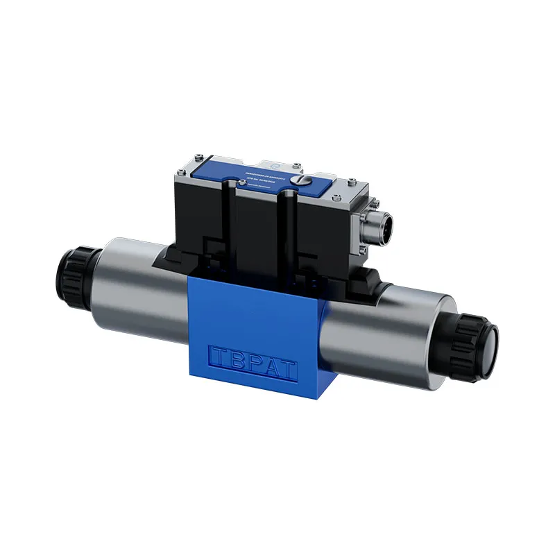
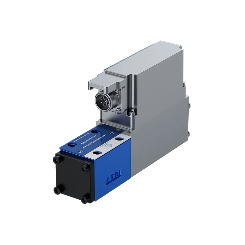
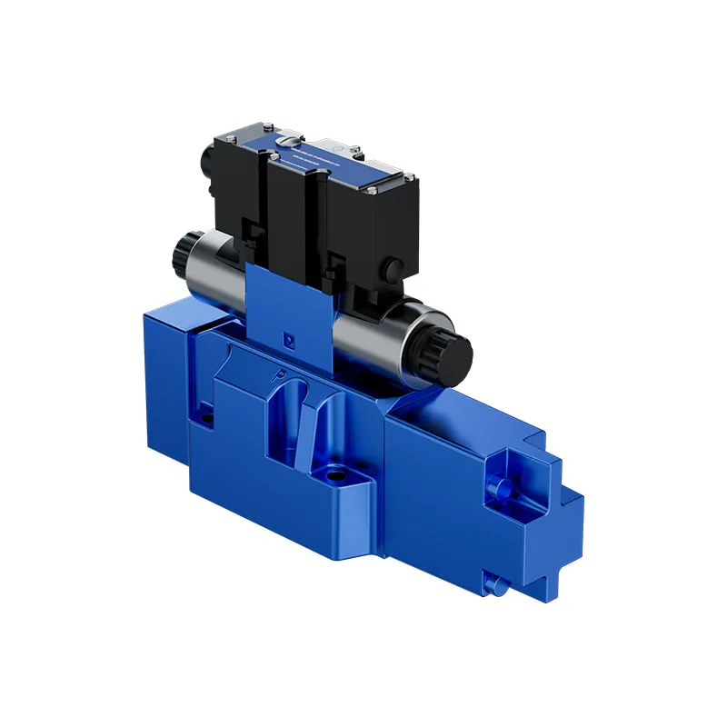
The 4WRLE proportional directional valve uses a pilot-operated arrangement for hydraulic control tasks. Its switched-off spool positions, pilot supply and drain connections must be reviewed together with the electrical command and the machine circuit.
- Pilot-operated proportional control
- Main spool position depends on the ordered version
- Pilot spool and sleeve construction
- Position, velocity or pressure-control applications
PRANCE HYDRAULIC · PRODUCT SERIES
cURL Too many subrequests by single Worker invocation. To configure this limit, refer to https://developers.cloudflare.com/workers/wrangler/configuration/#limits
Pilot-operated proportional directional spool valve · Match pilot supply, drain and spool symbol
The 4WRLE proportional directional valve uses a pilot-operated arrangement for hydraulic control tasks. Its switched-off spool positions, pilot supply and drain connections must be reviewed together with the electrical command and the machine circuit.
Model
✓
Request a QuotationTechnische Daten & Datenblatt anzeigen4WRLEPilot-operated proportional directional spool valve
Confirm the complete model and approved specification with Prance Hydraulic. Product-series references alone do not establish interchangeability.
Configuration review · Technical documentation · Product selection
Produktdetails
- Pilot-operated proportional control
- Main spool position depends on the ordered version
- Pilot spool and sleeve construction
- Position, velocity or pressure-control applications
CATEGORIES: Hydraulikventil, Proportionalventil
4WRLE Features & Application
Pilot-operated proportional control
Match the complete control option and its command requirements to the existing controller. Similar housings can use different control arrangements.
Main spool position depends on the ordered version
Specify the full MS order code, installation drawing and operating duty so the quotation can identify the proposed configuration.
Pilot spool and sleeve construction
Account for pilot or replenishment demand and the relevant pressure limits. Include filtration and the return or drain route in the circuit review.
Position, velocity or pressure-control applications
Match the complete control option and its command requirements to the existing controller. Similar housings can use different control arrangements.
4WRLE Specifications
| Series / model | 4WRLE |
|---|---|
| Product type | cURL Too many subrequests by single Worker invocation. To configure this limit, refer to https://developers.cloudflare.com/workers/wrangler/configuration/#limits |
| Design | Pilot-operated proportional directional spool valve |
| Circuit / selection | Match pilot supply, drain and spool symbol |
| Published nominal sizes | 10, 16, 25, 27 and 35 |
| Pilot arrangement | Confirm internal or external supply and drain from the order code |
4WRLE Selection & Configuration
The 4WRLE proportional directional valve uses a pilot-operated arrangement for hydraulic control tasks. Its switched-off spool positions, pilot supply and drain connections must be reviewed together with the electrical command and the machine circuit.
Define the required neutral or offset state before selecting the spool. A catalog fail-state description is not a guarantee of safe machine behavior. Confirm pilot-pressure limits, drain pressure and the exact electronics or feedback arrangement for the ordered code.

cURL Too many subrequests by single Worker invocation. To configure this limit, refer to https://developers.cloudflare.com/workers/wrangler/configuration/#limits.
cURL Too many subrequests by single Worker invocation. To configure this limit, refer to https://developers.cloudflare.com/workers/wrangler/configuration/#limits.
Hydraulic pumps · Hydraulic motors · Hydraulic valves
Send the MS nameplate, operating requirements and installation drawing for a configuration review before quoting.
- Model review — send the full model code or an existing nameplate photograph.
- Interface matching — confirm shaft, mounting flange, rotation and ports.
- Operating conditions — provide flow, pressure, speed, fluid and duty cycle.
- Documentation — request the relevant product data and drawings for your review.

4WRLE Buying Guide
Use this sequence to prepare the 4WRLE configuration for review and quotation.
- Select the circuit symbol and required de-energized spool position.
- State working flow, pressure and the pressure-drop condition for rated flow.
- Review spool overlap and command behavior during startup and switch-off.
- Confirm nominal size, subplate pattern, port and seal requirements.
- Match supply voltage, command input, connector and pin assignment.
- Review pilot supply, drain and feedback where the selected valve uses them.
- Approve the exact valve code, circuit drawing, quantity and documentation.

Selection, Documentation & Project Support

Selection Support
Learn more →Share your hydraulic circuit, operating point and installation requirements for a configuration discussion.
Flow · Pressure · Speed · Interfaces

Technical Resources
Learn more →Review product documentation, model codes and technical data before finalizing the specification.
Datasheets · Model codes · Drawings

Project Inquiries
Learn more →Send your required model, quantity, application and project requirements to discuss your inquiry.
Product inquiries · Configuration review
Configuration, Quantity & Delivery
Confirm the complete MS code, approved drawing and operating limits. Availability, quantity, documentation and delivery date are confirmed in the quotation.
Discuss Your 4WRLE Application
Send the full model code, operating duty, installation details and quantity.
Request a 4WRLE Quotation4WRLE Questions Before Ordering
What type of product is the 4WRLE?
4WRLE Pilot Operated Proportional Directional Valve. Design: Pilot-operated proportional directional spool valve. Match pilot supply, drain and spool symbol. Confirm the complete order code for the offered version.
Can a similar valve replace the 4WRLE?
cURL Too many subrequests by single Worker invocation. To configure this limit, refer to https://developers.cloudflare.com/workers/wrangler/configuration/#limits.
cURL Too many subrequests by single Worker invocation. To configure this limit, refer to https://developers.cloudflare.com/workers/wrangler/configuration/#limits
Select the circuit symbol and required de-energized spool position. State working flow, pressure and the pressure-drop condition for rated flow. Attach the nameplate, complete order code, installation drawing and required quantity.
4WRLE Technical Data & Documents
View 4WRLE catalog data and operating conditions
cURL Too many subrequests by single Worker invocation. To configure this limit, refer to https://developers.cloudflare.com/workers/wrangler/configuration/#limits.
Technische Daten(Für Anwendungen außerhalb dieser Werte sprechen Sie uns bitte an!)
Allgemein
| Größe | NG | 10 | 16 | 25 | 27 | 35 | |
| Einbaulage | Beliebig | ||||||
| Umgebungstemperaturbereich | ℃ | -20…+60 | |||||
| Maximale Lagerzeit | Jahre | 1 (bei Einhaltung der Lagerbedingungen; siehe Betriebsanleitung 07600-B) | |||||
| Sine test according to DIN EN 60068-2-6 | ▶ Ohne Dämpfungsplatte | 10 … 2000 Hz/ maximum of 10 g/10 cycles /3 axes | |||||
| ▶ Mit Dämpfungsplatte 1) | 10 … 2000 Hz/ maximum of 10 g/10 cycles /3 axes | ||||||
| Noise test according to DIN EN 60068-2-64 | ▶ Ohne Dämpfungsplatte | 20 … 2000 Hz/10 gRMS /30 g Peak /30 Min. /3 Achsen | |||||
| ▶ Mit Dämpfungsplatte 1) | 20 … 2000 Hz/10 gRMS /30 g Peak /24 h /3 Achsen | ||||||
| Transport shock according to DIN EN 60068-2-27 | ▶ Ohne Dämpfungsplatte | 15 g/11 ms /3 Schocks /3 Achsen | |||||
| ▶ Mit Dämpfungsplatte 1) | 15 g/11 ms /3 Schocks /3 Achsen | ||||||
| Schock gemäß DIN EN 60068-2-27 | ▶ Mit Dämpfungsplatte 1) | 35 g / 6 ms / 1000 Schöcke / 3 Achsen | |||||
| Gewicht | kg | 9 | 12 | 19 | 21 | 80 | |
| Maximale relative Luftfeuchtigkeit (keine Kondensation) | % | 95 | |||||
| Maximale Magnetoberflächentemperatur | ℃ | 120 (Einzeltätigkeit) | |||||
| MTTFd-Wert nach EN ISO 13849 | Jahre | 75 (weitere Details siehe Datenblatt 08012) | |||||
| Konformität | ▶CE according to EMC directive 2014/30/EU, tested according to EN 61000-6-2 and EN 61000-6-3 ▶RoHS directive 2015/65/EU ▶REACH ordinance (EC) no. 1907/2006 | ||||||
Hydraulisch
| Größe | NG | 10 | 16 | 25 | 27 | 35 | ||||||
| Maximum operating pressure | ▶ Anschlüsse A, B, P | |||||||||||
| – External pilot oil supply | Bar | 350 | 270 | 350 | ||||||||
| – Internal pilot oil supply | Bar | 280 | 270 | 280 | ||||||||
| ▶Port X | Bar | 280 | 270 | 280 | ||||||||
| ▶Ports T, Y | Bar | 250 | 210 | 250 | ||||||||
| Mindestvorsteuerdruck (Vorsteuerventil) | Bar | 10 | ||||||||||
| Maximaler Fluss | l/min | 300 | 800 | 1250 | 1850 | 4700 | ||||||
| Nennvolumenstrom (Δp = 5 bar/Steuerkante) 2) | l/min | 60/100 | 200/250 | 350/400 | 430/600 | 1000/1200/1500 | ||||||
| Steuerölstrom3) | ▶Symbol E, W | l/min | 2.4 | 3.5 | 7.5 | 23 | ||||||
| ▶Symbol V, Q3- | l/min | 4.5 | 11.5 | 22 | 29 | |||||||
| Maximum leakage flow (inlet pressure 100 bar) | ▶Symbol E, E1- – Main valve | l/min | 0.06 | 0.13 | 0.17 | 0.61 | ||||||
| – Main valve + pilot control valve | l/min | 0.14 | 0.28 | 0.42 | 1.01 | |||||||
| ▶Symbol w6-, W8- – Main valve | l/min | 0.12 | 0.26 | 0.35 | 1.23 | |||||||
| – Main valve + pilot control valve | l/min | 0.2 | 0.41 | 0.6 | 1.63 | |||||||
| Maximum zero flow (inlet pressure 100 bar) | cURL Too many subrequests by single Worker invocation. To configure this limit, refer to https://developers.cloudflare.com/workers/wrangler/configuration/#limits | l/min | 1.7 | 2.3 | 2.8 | 3.3 | 7.2 | |||||
| – Main valve + pilot control valve | l/min | 1.85 | 2.6 | 3.2 | 3.7 | 7.65 | ||||||
| cURL Too many subrequests by single Worker invocation. To configure this limit, refer to https://developers.cloudflare.com/workers/wrangler/configuration/#limits | l/min | 0.4 | 1.6 | 1.8 | 2.2 | 1.6 | ||||||
| – Main valve + pilot control valve | l/min | 0.55 | 1.9 | 2.2 | 2.6 | 2.05 | ||||||
| Durchflussentlastung Mittelstellung Δp = 5 bar/Steuerkante | A→T | B→T | A→T | B→T | A→T | B→T | A→T | B→T | A→T | B→T | ||
| ▶Symbol W6- | l/min | 2.8 | 2.8 | 4 | 4 | 6 | 6 | 6 | 6 | 25 | 25 | |
| ▶Symbol W8- | l/min | 2.8 | 1.4 | 4 | 2 | 6 | 3 | 6 | 3 | 25 | 12.5 | |
| Steuerölmenge | cURL Too many subrequests by single Worker invocation. To configure this limit, refer to https://developers.cloudflare.com/workers/wrangler/configuration/#limits | cm3 | 1.3 | 2.9 | 6.8 | 6.8 | 33..2 | |||||
| Hydraulikflüssigkeit | Siehe Tabelle | |||||||||||
| Viskositätsbereich | ▶ Empfohlen | mm2/s | cURL Too many subrequests by single Worker invocation. To configure this limit, refer to https://developers.cloudflare.com/workers/wrangler/configuration/#limits | |||||||||
| ▶Maximum | mm2/s | cURL Too many subrequests by single Worker invocation. To configure this limit, refer to https://developers.cloudflare.com/workers/wrangler/configuration/#limits | ||||||||||
| Temperaturbereich der Hydraulikflüssigkeit (durchströmt) | ℃ | cURL Too many subrequests by single Worker invocation. To configure this limit, refer to https://developers.cloudflare.com/workers/wrangler/configuration/#limits | ||||||||||
| Maximal zulässiger Verschmutzungsgrad der Hydraulikflüssigkeit; Reinheitsklasse nach ISO 4406 (c) | Klasse 18/16/134) | |||||||||||
| Hydraulikflüssigkeit | Klassifikation | Geeignete Dichtungsmaterialien | Standards | Datenblatt | |
| Mineralöle | HL, HLP | NBR, FKM | DIN 51524 | 90220 | |
| biologisch abbaubar | Unlöslich in Wasser | HETG | FKM | ISO 15380 | 90221 |
| HEES | FKM | ||||
| ▶In Wasser löslich | HEPG | FKM | ISO 15380 | ||
| flammhemmend | Wasserfrei | HFDU (Glykolbasis) | FKM | ISO 12922 | 90222 |
| HFDU (Esterbasis) | FKM | ||||
| HFDR | FKM | ||||
| Wasser enthaltend | HFC (Fuchs: Hydrotherm 46M, Renosafe 500; Petrofer: Ultra Safe 620; Houghton: Safe 620; Union: Carbide HP5046) | NBR | ISO 12922 | 90223 | |
| cURL Too many subrequests by single Worker invocation. To configure this limit, refer to https://developers.cloudflare.com/workers/wrangler/configuration/#limits. | |||||
Statisch/dynamisch
| Größe | NG | 10 | 16 | 25 | 27 | 35 | |
| Hysterese | % | <0,1 | |||||
| Antwortsensitivität | % | <0,05 | |||||
| Inversionsbereich | % | <0,08 | |||||
| Fertigungstoleranz qVmax | % | ≤10 | |||||
| cURL Too many subrequests by single Worker invocation. To configure this limit, refer to https://developers.cloudflare.com/workers/wrangler/configuration/#limits | ▶Symbole E, E1-, W6-, W8. | Frau | 25 | 37 | 36 | 36 | 55 |
| Abschaltverhalten (nach elektrischem Abschalten) | ▶Symbole E, E1-, W6-, W8- | Vorsteuerventil in Sicherheitsstellung, Hauptventil bewegt sich in die überdeckte, federzentrierte Mittelstellung | |||||
| ▶Symbol V, V1- | Pilot control valve in fail-safe position, main valve moves to spring-centered “offset position” (approx.6%, P→B/A→T) | ||||||
| ▶Symbol Q3 | Pilot control valve in fail-safe position, main valve moves to spring-centered “offset position” (P blocked, A/B to port T open) | ||||||
| Temperature drift (temperature range 20℃ … 80℃) | %/10 °C | Nullpunktverschiebung <0,25 | |||||
| Keine Entschädigung | Ex plant +1% | ||||||
Elektrische, integrierte Elektronik (OBE) – Schnittstelle “A1” und “F1”
| Relatives Tastverhältnis | % | 100 (Dauerbetrieb) | |
| Schutzart nach EN 60529 | IP 65 mit gesteckten und verriegelten Steckverbindern | ||
| Versorgungsspannung | VDC | 24 | |
| ▶ Terminal A | VDC | mind. 19 / max. 36 | |
| ▶ Terminal B | VDC | 0 | |
| Maximal zulässige Restwelligkeit | Vpp | 2.5 | |
| Maximale Leistungsaufnahme | VA | 40 | |
| Externe Absicherung | Österreich | 2.5 (Zeitverzögerung) | |
| Input, version “A1” | Differenzverstärker, Ri = 100 kΩ | ||
| ▶ Terminal D (UE) | VDC | 0…±10 | |
| ▶ Terminal E | VDC | 0 | |
| Input, version “F1” | Last, Rsh=200Ω | ||
| ▶ Terminal D (ID-E) | mA | 4…20 | |
| ▶ Terminal E (ID-E) | Aktuelles Schleifen-ID-E-Feedback | ||
| Maximale Spannung der differenziellen Eingänge gegen 0 V | D→B;E→B (max. 18 V) | ||
| Test signal, version “A1” | LVDT | ||
| ▶Terminal F(UTest) | V | 0 … ±10 | |
| ▶ Terminal C | Referenz 0 V | ||
| Test signal, version “F1” | LVDT signal 4 .. 20 mA on external load 200 … 500 0 maximum | ||
| ▶Terminal F(IF-C) | mA | 4…20 | |
| ▶Terminal C (IF-C) | Aktuelles Schleifen-IF-C-Feedback | ||
| Funktionserde und Schirmung | (EMV-gerechte Installation) | ||
| Anpassung | Im Werk kalibriert, siehe Ventilkennlinien | ||
Elektrische, integrierte Elektronik (OBE)-Schnittstelle “L1”
| Relatives Tastverhältnis | % | 100 (Dauerbetrieb) | |
| Schutzart nach EN 60529 | IP 65 mit gesteckten und verriegelten Steckverbindern | ||
| Versorgungsspannung | ▶Röhrenverstärker | VDC | 24 |
| – Pin 2 | VDC | mind. 18 / max. 30 | |
| – Pin 5 | VDC | 0 | |
| ▶IO-Link-Schnittstelle | VDC | 24 | |
| – Pin 1 | VDC | mind. 18 / max. 30 | |
| – Pin 3 | VDC | 0 | |
| Maximale Stromaufnahme | ▶Röhrenverstärker | A | 2 |
| ▶IO-Link-Schnittstelle | mA | 50 | |
| Maximale Restwelligkeit | Vpp | 1.3 | |
| Maximale Stromaufnahme | mA | 50 | |
| Mindestprozesszykluszeit | Frau | 0.6 | |
| Baudrate COM3 | kBaud (kbit/s) | 230.4 | |
| Erforderliche Master-Port-Klasse | Klasse B | ||
| Auflösung | ▶A/D-Wandler | Bit | 12 (Ventilöffnung 110%) |
| ▶D/A-Wandler | Bit | 12 (Ventilöffnung 110%) | |
| Funktionalboden | Über den Ventilblock bereitstellen | ||
| Anpassung | Im Werk kalibriert | ||
| Richtlinie | 10-Link Schnittstellen- und Systemspezifikation Version 1.1.2 | ||
Elektrische, integrierte Steuerungselektronik (OBE) – Schnittstelle “C6”
| Relatives Tastverhältnis | % | 100 (Dauerbetrieb) | |
| Schutzart nach EN 60529 | IP 65 mit gesteckten und verriegelten Steckverbindern | ||
| Versorgungsspannung | VDC | 24 | |
| ▶ Terminal A | VDC | mind. 19 / max. 36 | |
| ▶ Terminal B | VDC | 0 | |
| Maximal zulässige Restwelligkeit | Vpp | 2.5 | |
| Maximale Leistungsaufnahme | VA | 40 | |
| Externe Absicherung | AT | 2.5 (Zeitverzögerung) | |
| Eingabe | Last, RSchaffhausen= 200 Ω | ||
| ▶ Terminal D (ID-E) | mA | 0…±10 | |
| ▶ Terminal E (ID-E) | Aktuelle Schleife ID-E Feedback | ||
| Testsignal | LVDT signal 4 … 20 mA on external load 200 … 500Ω maximum | ||
| ▶ Terminal FIF-B) | mA | 4 … 20 | |
| ▶Terminal B(IF-B) | Aktuelle Schleife lrsfeedback | ||
| Funktionserde und Schirmung | (EMV-gerechte Installation) | ||
| Anpassung | Im Werk kalibriert, siehe Ventilkennlinien | ||
Related Selection Resources
Request a 4WRLE Quotation
Tell us your required configuration, quantity and application.
Ähnliche Produkte
cURL Too many subrequests by single Worker invocation. To configure this limit, refer to https://developers.cloudflare.com/workers/wrangler/configuration/#limits.

Bestellcode
| 01 | 02 | 03 | 04 | 05 | 06 | 07 | 08 | 09 | 10 | 11 | 12 | 13 | 14 | 15 | 16 | |||
| 4 | WRL | E | J | - | 4X | / | / | 24 | * |
| 01 | 4 Hauptanschlüsse | 4 |
| 02 | Wegeventil, vorgesteuert | WRL |
| 03 | Mit integrierter Elektronik (OBE) | E |
| 04 | Größe 10 | 10 |
| Größe 16 | 16 | |
| Größe 25 | 25 | |
| Größe 27 | 27 | |
| Größe 35 | 35 |
| 05 | Symbole z. B. E, E1-, W6- usw.; mögliche Version siehe Seite 4 |
Nennförderstrom (Δp = 5 bar / Steuerkante)
| 06 | -Größe 10 | |
| 60 l/min (nur Symbol E, E1-, W6-, W8-, V, V1-) | 60 | |
| 100 l/min | 100 | |
| -Größe 16 | ||
| 200 l/min (nur Symbole W6- und W8-) | 200 | |
| 250 l/min (nur Symbole E, E1-, V, V1- und Q3-) | 250 | |
| -Größe 25 | ||
| 350 l/min (nur Symbole W6- und W8-) | 350 | |
| 400 l/min (nur Symbole E, E1-, V, V1- und Q3-) | 400 | |
| -Größe 27 | ||
| 430 l/min (nur Symbol W6- und W8-) | 430 | |
| 600 l/min (nur Symbol E, E1-, V, V1- und Q3-) | 600 | |
| -Größe 35 | ||
| 1000 l/min (nur Symbol E, E1-, V, V1-) | 1000 | |
| 1200 l/min (nur Symbol W6- und W8-) | 1200 | |
| 1500 l/min (nur Symbol E, E1-, V, V1- und Q3-) | 1500 | |
Durchflusskennlinie
| 07 | Linear | L |
| Linear mit Feinstregelbereich (verfügbar für NG 10, andere Größen auf Anfrage) | P | |
| Progressiv mit linearer Feineinstellung (nur Symbol Q3-) | M |
| 08 | Überlappungssprung (Öffnungspunkt 5% mit geschlossenem Ventil; nur Symbole E, E1-, W6-, W8-) | J |
| 09 | Baureihe 40 ... 49 (40 ... 49: unveränderte Einbau- und Montageabmessungen) | 4X |
Dichtungsmaterial (Verträglichkeit der Dichtungen mit der verwendeten Hydraulikflüssigkeit beachten)
| 10 | NBR-Dichtungen | M |
| FKM-Dichtungen | V |
Steuerölstrom
| 11 | Externe Steölversorgung, externer Steuerölrücklauf | XY |
| Interne Vorsteuerölversorgung, externe Vorsteuerölrücklauf | PY | |
| Interne Steuerölversorgung, interner Steuerölrücklauf | PT | |
| Externe Steuerölversorgung, interne Steuerölrückführung | XT |
| 12 | Ohne Dämpfungsplatte | ohne Bezeichnung |
| Mit Dämpfungsplatte | D |
| 13 | Versorgungsspannung 24 V | 24 |
Schnittstellen der Steuerelektronik
| 14 | Sollwerteingabe ±10V | A1 |
| Sollwerteingabe 4 ... 20 mA | F1 | |
| IO-Link-Schnittstelle | L1 | |
| Sollwert ±10 mA, Istwert 4 ... 20 mA, Freigabe (Stecker 6+PE) | C6 |
| 15 | Ohne Elektronikschutzmembran | ohne Bezeichnung |
| Mit Elektronikschutzmembran | -967 |
| 16 | Für weitere Details siehe den Klartext | * |
Technische Daten(Für Anwendungen außerhalb dieser Werte sprechen Sie uns bitte an!)
Allgemein
| Größe | NG | 10 | 16 | 25 | 27 | 35 | |
| Einbaulage | Beliebig | ||||||
| Umgebungstemperaturbereich | ℃ | -20...+60 | |||||
| Maximale Lagerzeit | Jahre | 1 (bei Einhaltung der Lagerbedingungen; siehe Betriebsanleitung 07600-B) | |||||
| Sinustest gemäß nach DIN EN 60068-2-6 |
▶ Ohne Dämpfungsplatte | 10 ... 2000 Hz/ maximal 10 g/10 Zyklen /3 Achsen | |||||
| ▶ Mit Dämpfungsplatte 1) | 10 ... 2000 Hz/ maximal 10 g/10 Zyklen /3 Achsen | ||||||
| Geräuschprüfung gemäß nach DIN EN 60068-2-64 |
▶ Ohne Dämpfungsplatte | 20 ... 2000 Hz/10 gRMS /30 g Peak /30 Min. /3 Achsen | |||||
| ▶ Mit Dämpfungsplatte 1) | 20 ... 2000 Hz/10 gRMS /30 g Peak /24 h /3 Achsen | ||||||
| Transportschock gemäß nach DIN EN 60068-2-27 |
▶ Ohne Dämpfungsplatte | 15 g/11 ms /3 Schocks /3 Achsen | |||||
| ▶ Mit Dämpfungsplatte 1) | 15 g/11 ms /3 Schocks /3 Achsen | ||||||
| Schock gemäß DIN EN 60068-2-27 | ▶ Mit Dämpfungsplatte 1) | 35 g / 6 ms / 1000 Schöcke / 3 Achsen | |||||
| Gewicht | kg | 9 | 12 | 19 | 21 | 80 | |
| Maximale relative Luftfeuchtigkeit (keine Kondensation) | % | 95 | |||||
| Maximale Magnetoberflächentemperatur | ℃ | 120 (Einzeltätigkeit) | |||||
| MTTFd-Wert nach EN ISO 13849 | Jahre | 75 (weitere Details siehe Datenblatt 08012) | |||||
| Konformität | ▶ CE gemäß EMV-Richtlinie 2014/30/EU, geprüft nach EN 61000-6-2 und EN 61000-6-3 ▶RoHS-Richtlinie 2015/65/EU ▶REACH-Verordnung (EG) Nr. 1907/2006 |
||||||
1)Nicht empfohlen für Anwendungen mit überwiegend niederfrequenter Anregung < 300 Hz
Hydraulisch
| Größe | NG | 10 | 16 | 25 | 27 | 35 | ||||||
| Maximum Betriebsdruck |
▶ Anschlüsse A, B, P | |||||||||||
| - Externe Steuerölversorgung | Bar | 350 | 270 | 350 | ||||||||
| - Interne Steuerölversorgung | Bar | 280 | 270 | 280 | ||||||||
| ▶Port X | Bar | 280 | 270 | 280 | ||||||||
| ▶Ports T, Y | Bar | 250 | 210 | 250 | ||||||||
| Mindestvorsteuerdruck (Vorsteuerventil) | Bar | 10 | ||||||||||
| Maximaler Fluss | l/min | 300 | 800 | 1250 | 1850 | 4700 | ||||||
| Nennvolumenstrom (Δp = 5 bar/Steuerkante) 2) | l/min | 60/100 | 200/250 | 350/400 | 430/600 | 1000/1200/1500 | ||||||
| Steuerölstrom3) | ▶Symbol E, W | l/min | 2.4 | 3.5 | 7.5 | 23 | ||||||
| ▶Symbol V, Q3- | l/min | 4.5 | 11.5 | 22 | 29 | |||||||
| Maximum Leckagefluss (Eingangsdruck 100 bar) |
▶Symbol E, E1- - Hauptventil |
l/min | 0.06 | 0.13 | 0.17 | 0.61 | ||||||
| - Hauptventil + Vorsteuerventil | l/min | 0.14 | 0.28 | 0.42 | 1.01 | |||||||
| ▶Symbol w6-, W8- - Hauptventil |
l/min | 0.12 | 0.26 | 0.35 | 1.23 | |||||||
| - Hauptventil + Vorsteuerventil | l/min | 0.2 | 0.41 | 0.6 | 1.63 | |||||||
| Maximum kein Durchfluss (Eingangsdruck 100 bar) |
▶Symbol V, V1- - Hauptventil |
l/min | 1.7 | 2.3 | 2.8 | 3.3 | 7.2 | |||||
| - Hauptventil + Vorsteuerventil | l/min | 1.85 | 2.6 | 3.2 | 3.7 | 7.65 | ||||||
| ▶Symbol Q3- - Hauptventil |
l/min | 0.4 | 1.6 | 1.8 | 2.2 | 1.6 | ||||||
| - Hauptventil + Vorsteuerventil | l/min | 0.55 | 1.9 | 2.2 | 2.6 | 2.05 | ||||||
| Durchflussentlastung Mittelstellung Δp = 5 bar/Steuerkante | A→T | B→T | A→T | B→T | A→T | B→T | A→T | B→T | A→T | B→T | ||
| ▶Symbol W6- | l/min | 2.8 | 2.8 | 4 | 4 | 6 | 6 | 6 | 6 | 25 | 25 | |
| ▶Symbol W8- | l/min | 2.8 | 1.4 | 4 | 2 | 6 | 3 | 6 | 3 | 25 | 12.5 | |
| Steuerölmenge | 0...100% | cm3 | 1.3 | 2.9 | 6.8 | 6.8 | 33..2 | |||||
| Hydraulikflüssigkeit | Siehe Tabelle | |||||||||||
| Viskositätsbereich | ▶ Empfohlen | mm2/s | 20...100 | |||||||||
| ▶Maximum | mm2/s | 10...800 | ||||||||||
| Temperaturbereich der Hydraulikflüssigkeit (durchströmt) | ℃ | -20...+70 | ||||||||||
| Maximal zulässiger Verschmutzungsgrad der Hydraulikflüssigkeit; Reinheitsklasse nach ISO 4406 (c) | Klasse 18/16/134) | |||||||||||
2) Fluss für abweichendes Δp (Steuerkante): qx=qVnom×√(Δpx/5)
3) An den Anschlüssen X und Y mit einem stufenweisen Eingangssignal von 0 … 100% (Pilotdruck 100 bar)
Bei Hydrauliksystemen müssen die für die Komponenten vorgeschriebenen Reinheitsklassen eingehalten werden. Eine effektive Filtration verhindert Störungen und erhöht gleichzeitig die Lebensdauer der Komponenten.
| Hydraulikflüssigkeit | Klassifikation | Geeignete Dichtungsmaterialien | Standards | Datenblatt | |
| Mineralöle | HL, HLP | NBR, FKM | DIN 51524 | 90220 | |
| biologisch abbaubar | Unlöslich in Wasser | HETG | FKM | ISO 15380 | 90221 |
| HEES | FKM | ||||
| ▶In Wasser löslich | HEPG | FKM | ISO 15380 | ||
| flammhemmend | Wasserfrei | HFDU (Glykolbasis) | FKM | ISO 12922 | 90222 |
| HFDU (Esterbasis) | FKM | ||||
| HFDR | FKM | ||||
| Wasser enthaltend | HFC (Fuchs: Hydrotherm 46M, Renosafe 500; Petrofer: Ultra Safe 620; Houghton: Safe 620; Union: Carbide HP5046) | NBR | ISO 12922 | 90223 | |
| Wichtige Hinweise zu Hydraulikflüssigkeiten: ▶Für weitere Informationen und Daten zur Verwendung anderer Hydraulikflüssigkeiten beachten Sie bitte die oben genannten Datenblätter oder kontaktieren Sie uns. Hinsichtlich der technischen VentilaterData (Temperatur, Druckbereich, Lebensdauer, Wartungsintervalle etc.) kann es Einschränkungen geben. Die Zündtemperatur der verwendeten Hydraulikflüssigkeit muss 50 K höher sein als die maximale Oberflächentemperatur. ▶ Biologisch abbaubares und flammhemmendes Wasser: Werden Bauteile mit galvanischer Zinkbeschichtung (z. B. Ausführung "J3" oder "J5") oder zinkhaltige Teile verwendet, können geringe Mengen gelösten Zinks in das Hydrauliksystem gelangen und eine beschleunigte Alterung der Hydraulikflüssigkeit verursachen. Als chemisches Reaktionsprodukt kann Zinkseife entstehen, die insbesondere in Verbindung mit lokalem Wärmeeintrag Filter, Düsen und Magnetventile zusetzen kann. ▶ Flammschutzmittelhaltiges Wasser: -Aufgrund der erhöhten Kavitationsneigung bei HFC-Hydraulikflüssigkeiten kann sich die Lebensdauer des Bauteils im Vergleich zum Einsatz mit mineralölbasiertem HLP um bis zu 30 % verkürzen. Um den Kavitationseffekt zu verringern, wird empfohlen – sofern an der Anlage möglich –, den Rücklaufdruck an den Anschlüssen T auf ca. 20 % des Druckunterschieds am Bauteil abzustützen. -Abhängig von der verwendeten Hydraulikflüssigkeit dürfen die maximale Umgebungs- und Hydraulikflüssigkeitstemperatur 50 °C nicht überschreiten. Um den Wärmeeintrag in das Bauteil zu reduzieren, ist das Sollwertprofil für Proportional- und High-Response-Ventile anzupassen. |
|||||
Statisch/dynamisch
| Größe | NG | 10 | 16 | 25 | 27 | 35 | |
| Hysterese | % | <0,1 | |||||
| Antwortsensitivität | % | <0,05 | |||||
| Inversionsbereich | % | <0,08 | |||||
| Fertigungstoleranz qVmax | % | ≤10 | |||||
| Betätigungszeit für 0 … 100% bei X = 210 bar | ▶Symbole E, E1-, W6-, W8. | Frau | 25 | 37 | 36 | 36 | 55 |
| Abschaltverhalten (nach elektrischem Abschalten) | ▶Symbole E, E1-, W6-, W8- | Vorsteuerventil in Sicherheitsstellung, Hauptventil bewegt sich in die überdeckte, federzentrierte Mittelstellung | |||||
| ▶Symbol V, V1- | Pilotventil in Fail-Safe-Stellung, Hauptventil bewegt sich in die federzentrierte "Offset-Stellung" (ca. 6%, P→B/A→T) | ||||||
| ▶Symbol Q3 | Vorseuerventil in Sicherheitsstellung, Hauptventil bewegt sich in die federzentrierte "Mittelstellung" (P gesperrt, A/B zu Anschluss T offen) | ||||||
| Temperaturdrift (Temperaturbereich 20 °C … 80 °C) | %/10 °C | Nullpunktverschiebung <0,25 | |||||
| Keine Entschädigung | Ehemaliges Werk +1% |
||||||
Elektrische, integrierte Elektronik (OBE) – Schnittstelle “A1” und “F1”
| Relatives Tastverhältnis | % | 100 (Dauerbetrieb) | |
| Schutzart nach EN 60529 | IP 65 mit gesteckten und verriegelten Steckverbindern | ||
| Versorgungsspannung | VDC | 24 | |
| ▶ Terminal A | VDC | mind. 19 / max. 36 | |
| ▶ Terminal B | VDC | 0 | |
| Maximal zulässige Restwelligkeit | Vpp | 2.5 | |
| Maximale Leistungsaufnahme | VA | 40 | |
| Externe Absicherung | Österreich | 2.5 (Zeitverzögerung) | |
| Eingabe, Version "A1" | Differenzverstärker, Ri = 100 kΩ | ||
| ▶ Terminal D (UE) | VDC | 0...±10 | |
| ▶ Terminal E | VDC | 0 | |
| Eingabe, Version "F1" | Last, Rsh=200Ω | ||
| ▶ Terminal D (ID-E) | mA | 4...20 | |
| ▶ Terminal E (ID-E) | Aktuelles Schleifen-ID-E-Feedback | ||
| Maximale Spannung der differenziellen Eingänge gegen 0 V | D→B;E→B (max. 18 V) | ||
| Testsignal, Version "A1" | LVDT | ||
| ▶Terminal F(UTest) | V | 0 ... ±10 | |
| ▶ Terminal C | Referenz 0 V | ||
| Testsignal, Version "F1" | LVDT-Signal 4 .. 20 mA an externer Last 200 ... 500 Ω Maximum | ||
| ▶Terminal F(IF-C) | mA | 4...20 | |
| ▶Terminal C (IF-C) | Aktuelles Schleifen-IF-C-Feedback | ||
| Funktionserde und Schirmung | (EMV-gerechte Installation) | ||
| Anpassung | Im Werk kalibriert, siehe Ventilkennlinien | ||
Elektrische, integrierte Elektronik (OBE)-Schnittstelle “L1”
| Relatives Tastverhältnis | % | 100 (Dauerbetrieb) | |
| Schutzart nach EN 60529 | IP 65 mit gesteckten und verriegelten Steckverbindern | ||
| Versorgungsspannung | ▶Röhrenverstärker | VDC | 24 |
| - Pin 2 | VDC | mind. 18 / max. 30 | |
| - Pin 5 | VDC | 0 | |
| ▶IO-Link-Schnittstelle | VDC | 24 | |
| - Pin 1 | VDC | mind. 18 / max. 30 | |
| - Pin 3 | VDC | 0 | |
| Maximale Stromaufnahme | ▶Röhrenverstärker | A | 2 |
| ▶IO-Link-Schnittstelle | mA | 50 | |
| Maximale Restwelligkeit | Vpp | 1.3 | |
| Maximale Stromaufnahme | mA | 50 | |
| Mindestprozesszykluszeit | Frau | 0.6 | |
| Baudrate COM3 | kBaud (kbit/s) | 230.4 | |
| Erforderliche Master-Port-Klasse | Klasse B | ||
| Auflösung | ▶A/D-Wandler | Bit | 12 (Ventilöffnung 110%) |
| ▶D/A-Wandler | Bit | 12 (Ventilöffnung 110%) | |
| Funktionalboden | Über den Ventilblock bereitstellen | ||
| Anpassung | Im Werk kalibriert | ||
| Richtlinie | 10-Link Schnittstellen- und Systemspezifikation Version 1.1.2 | ||
Elektrische, integrierte Steuerungselektronik (OBE) – Schnittstelle “C6”
| Relatives Tastverhältnis | % | 100 (Dauerbetrieb) | |
| Schutzart nach EN 60529 | IP 65 mit gesteckten und verriegelten Steckverbindern | ||
| Versorgungsspannung | VDC | 24 | |
| ▶ Terminal A | VDC | mind. 19 / max. 36 | |
| ▶ Terminal B | VDC | 0 | |
| Maximal zulässige Restwelligkeit | Vpp | 2.5 | |
| Maximale Leistungsaufnahme | VA | 40 | |
| Externe Absicherung | AT | 2.5 (Zeitverzögerung) | |
| Eingabe | Last, RSchaffhausen= 200 Ω | ||
| ▶ Terminal D (ID-E) | mA | 0...±10 | |
| ▶ Terminal E (ID-E) | Aktuelle Schleife ID-E Feedback | ||
| Testsignal | LVDT-Signal 4 ... 20 mA an externer Last 200 ... 500 Ω Maximum | ||
| ▶ Terminal FIF-B) | mA | 4 ... 20 | |
| ▶Terminal B(IF-B) | Aktuelle Schleife lrsfeedback | ||
| Funktionserde und Schirmung | (EMV-gerechte Installation) | ||
| Anpassung | Im Werk kalibriert, siehe Ventilkennlinien | ||