Wenzhou Prance Hydraulic Equipment Co., Ltd


A10VSO Series 52 Variable Piston Pump
The A10VSO Series 52 page covers an open-circuit variable displacement pump. Keep the Series 52 identity in the request and compare the exact control, shaft and ports; a Series 53 photograph or a similar displacement does not establish a replacement.
- Series 52 model reference
- Open-circuit swashplate pump
- Variable displacement flow
- Control and interface selection by full code
PRANCE HYDRAULIC · PRODUCT SERIES
A10VSO Series 52 Variable Piston Pump
Axial piston; variable swashplate · Open circuit
The A10VSO Series 52 page covers an open-circuit variable displacement pump. Keep the Series 52 identity in the request and compare the exact control, shaft and ports; a Series 53 photograph or a similar displacement does not establish a replacement.
Model
✓
Request a QuotationView Technical Data & DatasheetA10VSO Series 52Axial piston; variable swashplate
Confirm the complete model and approved specification with Prance Hydraulic. Product-series references alone do not establish interchangeability.
Configuration review · Technical documentation · Product selection
Product Details
- Series 52 model reference
- Open-circuit swashplate pump
- Variable displacement flow
- Control and interface selection by full code
CATEGORIES: Piston Pump, Variable Displacement Pump
A10VSO Series 52 Features & Application
Series 52 model reference
Include the series and all order-code suffixes in the enquiry. A common nominal size does not establish compatibility.
Open-circuit swashplate pump
Review normal running, startup and reversal where applicable. The pressure and flow requirements can differ between operating states.
Variable displacement flow
Specify the displacement range or switching arrangement and verify performance at each required setting.
Control and interface selection by full code
Match the complete control option and its command requirements to the existing controller. Similar housings can use different control arrangements.
A10VSO Series 52 Specifications
| Series / model | A10VSO Series 52 |
|---|---|
| Product type | A10VSO Series 52 Variable Piston Pump |
| Design | Axial piston; variable swashplate |
| Circuit / selection | Open circuit |
| Series | 52 |
| Published family nominal-size table | 10, 18, 28, 45, 60, 63, 72, 85 and 100; availability is configuration-specific |
A10VSO Series 52 Selection & Configuration
The A10VSO Series 52 page covers an open-circuit variable displacement pump. Keep the Series 52 identity in the request and compare the exact control, shaft and ports; a Series 53 photograph or a similar displacement does not establish a replacement.
Select the displacement from the required flow at the working speed and review the full pressure-duty cycle. Confirm which sizes and controls are offered for the exact A10VSO Series 52 code, rather than treating a combined series table as an availability list.

Your Application.
The Right Configuration.
Hydraulic pumps · Hydraulic motors · Hydraulic valves
Send the A10VSO Series 52 nameplate, operating requirements and installation drawing for a configuration review before quoting.
- Model review — send the full model code or an existing nameplate photograph.
- Interface matching — confirm shaft, mounting flange, rotation and ports.
- Operating conditions — provide flow, pressure, speed, fluid and duty cycle.
- Documentation — request the relevant product data and drawings for your review.

A10VSO Series 52 Buying Guide
Use this sequence to prepare the A10VSO Series 52 configuration for review and quotation.
- Define required flow at the actual drive speed and continuous pressure.
- Identify peak pressure, duration and the work cycle.
- Confirm the selected displacement control and any auxiliary-drive requirement.
- Match rotation viewed from the shaft end, shaft, flange and ports.
- Review inlet conditions, drain routing and the installation envelope.
- Confirm fluid, viscosity, temperature, filtration and seals.
- Approve the complete model, control, drawing, quantity and delivery terms.

Selection, Documentation & Project Support

Selection Support
Learn more →Share your hydraulic circuit, operating point and installation requirements for a configuration discussion.
Flow · Pressure · Speed · Interfaces

Technical Resources
Learn more →Review product documentation, model codes and technical data before finalizing the specification.
Datasheets · Model codes · Drawings

Project Inquiries
Learn more →Send your required model, quantity, application and project requirements to discuss your inquiry.
Product inquiries · Configuration review
Configuration, Quantity & Delivery
Confirm the complete A10VSO Series 52 code, approved drawing and operating limits. Availability, quantity, documentation and delivery date are confirmed in the quotation.
Discuss Your A10VSO Series 52 Application
Send the full model code, operating duty, installation details and quantity.
Request a A10VSO Series 52 QuotationA10VSO Series 52 Questions Before Ordering
What type of product is the A10VSO Series 52?
A10VSO Series 52 Variable Piston Pump. Design: Axial piston; variable swashplate. Open circuit. Confirm the complete order code for the offered version.
Can a similar pump replace the A10VSO Series 52?
Only after checking the operating duty, interfaces and control requirements. A matching displacement, nominal size or photograph does not establish interchangeability. Compare the approved drawings and complete codes.
Which data is needed for a quotation?
Define required flow at the actual drive speed and continuous pressure. Identify peak pressure, duration and the work cycle. Attach the nameplate, complete order code, installation drawing and required quantity.
A10VSO Series 52 Technical Data & Documents
View A10VSO Series 52 catalog data and operating conditions
Catalog reference for the model rows and variants explicitly identified below. Keep each value with its unit, duty condition and footnotes. Family tables may include related versions; confirm the complete offered code and approved data before ordering.
Technical data
| Size | NG | 10 | 18 | 28 | 45 | 60 | 63 | 72 | 85 | 100 | ||
| Displacement, geometric, per revolution | Vg max | cm3 | 10.5 | 18 | 28 | 45 | 60 | 63 | 72 | 85 | 100 | |
| Rotational speed maximum1) | at Vg max | nnom | rpm | 3600 | 3300 | 3000 | 26004) | 2700 | 2600 | 2600 | 2500 | 2300 |
| at Vg <Vg max 2) | nmax adm. | rpm | 4320 | 3960 | 3600 | 3120 | 3140 | 3140 | 3140 | 3000 | 2500 | |
| Flow | at nnom and Vg max | qv | I/min | 37 | 59 | 84 | 117 | 162 | 163 | 187 | 212 | 230 |
| at nE = 1500 rpm | qvE | I/min | 15 | 27 | 42 | 68 | 90 | 95 | 108 | 128 | 150 | |
| Power | With Nnom, Vg max and Δp = 250 bar | P | kW | 16 | 25 | 35 | 49 | 65 | 68 | 77 | 89 | 96 |
| at nE= 1500 rpm | PE | kW | 7 | 11 | 18 | 28 | 37 | 39 | 45 | 53 | 62 | |
| Torque | at Vg max and Δp = 250 bar | M | Nm | 42 | 71 | 111 | 179 | 238 | 250 | 286 | 338 | 398 |
| at Vg max and Δp = 100 bar | M | Nm | 17 | 29 | 45 | 72 | 95 | 100 | 114 | 135 | 159 | |
| Rotary stiffness Drive shaft | S | c | Nm/rad | 9200 | 11000 | 22300 | 37500 | 65500 | 65500 | 65500 | 143000 | 143000 |
| R | c | Nm/rad | – | 14800 | 26300 | 41000 | 69400 | 69400 | 69400 | 152900 | 152900 | |
| U | c | Nm/rad | 6800 | 8000 | 16700 | 30000 | 49200 | 49200 | 49200 | 102900 | 102900 | |
| W | c | Nm/rad | – | – | 19900 | 34400 | 54000 | 54000 | 54000 | 117900 | 117900 | |
| P | c | Nm/rad | 10700 | – | – | – | – | – | – | – | – | |
| Moment of inertia of the rotary group | JTW | Kgm2 | 0.0006 | 0.0009 | 0.0017 | 0.003 | 0.0056 | 0.0056 | 0.0056 | 0.012 | 0.012 | |
| Maximum angular acceleration3) | α | rad/s2 | 8000 | 6800 | 5500 | 4000 | 3300 | 3300 | 3300 | 2700 | 2700 | |
| Case volume | V | L | 0.2 | 0.25 | 0.3 | 0.5 | 0.8 | 0.8 | 0.8 | 1 | 1 | |
| Weight without through drive (approx.) Weight with through drive (approx.) | m | kg | 8 | 11.5 | 15 | 18 | 22 | 22 | 22 | 36 | 36 | |
| – | 13 | 18 | 24 | 28 | 28 | 28 | 45 | 45 | ||||
Determining the operating characteristics
Permissible radial and axial forces on the drive shaft
| Size | NG | 10 | 18 | 28 | 45 | 60/63 | 72 | 85 | 100 | ||
| Maximum radial force at a/2 |  |
Fq max | N | 250 | 350 | 1200 | 1500 | 1700 | 1500 | 2000 | 2000 |
| Maximum axial force | 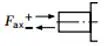 |
±Fax max | N | 400 | 700 | 1000 | 1500 | 2000 | 1500 | 3000 | 3000 |
Permissible input and through-drive torques
| Size | 10 | 18 | 28 | 45 | 60/63 | 72 | 85 | 100 | |||
| Maximum input torque on drive shaft2) | |||||||||||
| S | ME max | Nm | 126 | 124 | 198 | 319 | 630 | 630 | 1157 | 1157 | |
| ∅ | in | 3/4 | 3/4 | 7/8 | 1 | 1 1/4 | 1 1/4 | 1 1/2 | 1 1/2 | ||
| R | ME max | Nm | – | 160 | 250 | 400 | 650 | 650 | 1215 | 1215 | |
| ∅ | in | – | 3/4 | 7/8 | 1 | 1 1/4 | 1 1/4 | 1 1/2 | 1 1/2 | ||
| U | ME max | Nm | 60 | 59 | 105 | 188 | 306 | 306 | 628 | 628 | |
| ∅ | in | 5/8 | 5/8 | 3/4 | 7/8 | 1 | 1 | 1 1/4 | 1 1/4 | ||
| W | ME max | Nm | – | – | 140 | 220 | 396 | 383 | 650 | 650 | |
| ∅ | in | – | – | 3/4 | 7/8 | 1 | 1 | 1 1/4 | 1 1/4 | ||
| P | ME max | Nm | 90 | – | – | – | – | – | – | – | |
| ∅ | mm | 18 | – | – | – | – | – | – | – | ||
| Maximum through-drive torque | |||||||||||
| S | MD max | Nm | – | 108 | 160 | 319 | 484 | 484 | 698 | 698 | |
| R | MD max | Nm | – | 120 | 176 | 365 | 484 | 484 | 698 | – | |
| U | MD max | Nm | – | 59 | 105 | 188 | 306 | 306 | 628 | 628 | |
| W | MD max | Nm | – | – | 140 | 220 | 396 | 383 | 650 | 650 | |
Distribution of torques
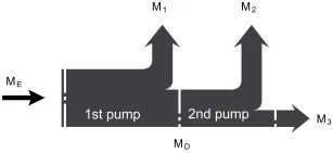
| Input torque | ME=M1+M2+M3 |
| ME < ME max | |
| Through∙drive torque | MD=M2+M3 |
| MD < MD max |
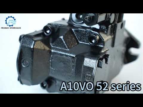
Watch A10VSO Series 52 Product Video
Related Selection Resources
Request a A10VSO Series 52 Quotation
Tell us your required configuration, quantity and application.
Related Products
Compare related hydraulic pumps and confirm the complete configuration for your application.


Type code series 52
| 01 | 02 | 03 | 04 | 05 | 06 | 07 | 08 | 09 | 10 | 11 | 12 | ||
| A10V(S) | ○ | / | 32 | - | v |
Axial piston unit
| 10 | 28 | 45 | 60 | 85 | |||
| 01 | Swashplate design, variable, nominal pressure 250 bar, maximum pressure 315 bar | ● | - | - | - | - | A10VS |
| - | ● | ● | ● | ● | A10V |
Operation mode
| 02 | Pump, open circuit | ○ |
Size(NG)
| 03 | Geometric displacement, see table of values on page 10 | 10 | 28 | 45 | 60 | 85 |
Control device
| 04 | Pressure controller | hydraulic | ● | ● | ● | ● | ● | DR | ||||
| with flow controller | hydraulic | X-T open | ● | ● | ● | ● | ● | DFR | ||||
| X-T plugged | with flushing function | ● | ● | ● | ● | ● | DFR1 | |||||
| without flushing function | ● | ● | ● | ● | ● | DRSC | ||||||
| with pressure cut-off | hydraulic | remotely controlled | ● | ● | ● | ● | ● | DRG | ||||
| electrical | negative control | U=12V | ● | ● | ● | ● | ● | ED71 | ||||
| U=24V | ● | ● | ● | ● | ● | ED72 | ||||||
| electrical | positive control | U=12V | ● | ● | ● | ● | ● | ER71 | ||||
| U=24V | ● | ● | ● | ● | ● | ER72 | ||||||
| Differential pressure control | electric control (negative control) | ● | ● | ● | ● | ○ | EF..1) | |||||
Series
| 10 | 28 | 45 | 60 | 85 | |||
| 05 | Series 5, index 2 | ● | ● | ● | ● | ● | 52 |
Direction of rotation
| 06 | Viewed on drive shaft | clockwise | R |
| counter-clockwise | L |
Sealing material
| 07 | FKM (fluoroelastomer) | V |
Drive shaft
| 08 | Splined shaft
IS0 3019-1 |
standard shaft | ● | ● | ● | ● | ● | S |
| similar to shaft "S" however for higher input torque | - | ● | ● | ● | ● | R | ||
| reduced diameter, limited suitability for through drive | ● | ● | ● | ● | ● | U | ||
| similar to shaft "U", however for higher torque only conditionally suitable for mounting with through drive. | - | ● | ● | ● | ● | W | ||
| Parallel keyed shaft DIN 6885 limited suitability for through drive | ● | - | - | - | - | P | ||
Mounting flange
| 09 | ISO 3019-2 (ISO) | 2-hole | ● | - | - | - | - | A |
| ISO 3019-1 (SAE) | 4-hole | ● | ● | ● | ● | ● | C | |
| 4-hole | - | - | - | ● | - | D |
Working port
| 10 | 28 | 45 | 60 | 85 | |||||
| 10 | SAE flange ports Fastening thread metric | rear | not for through drive | - | ● | ● | ● | ● | 11 |
| laterally opposite | for through drive | - | ● | ● | ● | ● | 12 | ||
| at side,offset 90° | not for through drive;
available for counter-clockwise rotation only |
- | - | ● | - | - | 13 | ||
| Threaded port metric | rear | not for through drive | ● | - | - | - | - | 14 |
Through drive
| 11 | Flange IS0 3019-1
Diameter |
Hub for splined shaft1)
Diameter |
045 | 071 | 100 | 140 | 180 | ||
| without through drive | ● | ● | ● | ● | ● | N00 | |||
| 82-2 (A) | 5/8 in | 9T 16/32DP | - | ● | ● | ● | ● | K01 | |
| 3/4 in | 11T 16/32DP | - | ● | ● | ● | ● | K52 | ||
| 101-2 (B) | 7/8in | 13T 16/32DP | - | ● | ● | ● | ● | K68 | |
| 1in | 15T 16/32DP | - | - | ● | ● | ● | K04 | ||
| 127-4 (C) | 1 1/4in | 14T 12/24DP | - | - | - | ● | ● | K15 | |
| 1 1/2 in | 17T12/24DP | - | - | - | - | ● | K16 | ||
| 127-2 (C) | 1 1/4 in | 14T 12/24DP | - | - | - | - | ● | K07 | |
| 1 1/2 in | 17T 12/24DP | - | - | - | - | ● | K24 | ||
Connectors for solenoids
| 12 | Without connector (without solenoid, only for hydraulic controls, without signs) | ● | ● | ● | ● | ● | |
| DEUTSCH - molded connector, 2-pin, without suppressor diode (for electric control) | - | ● | ● | ● | ● | P |
•= Available ○ = On request - = Not available
Technical data
| Size | NG | 10 | 18 | 28 | 45 | 60 | 63 | 72 | 85 | 100 | ||
| Displacement, geometric, per revolution | Vg max | cm3 | 10.5 | 18 | 28 | 45 | 60 | 63 | 72 | 85 | 100 | |
| Rotational speed
maximum1) |
at Vg max | nnom | rpm | 3600 | 3300 | 3000 | 26004) | 2700 | 2600 | 2600 | 2500 | 2300 |
| at Vg <Vg max 2) | nmax adm. | rpm | 4320 | 3960 | 3600 | 3120 | 3140 | 3140 | 3140 | 3000 | 2500 | |
| Flow | at nnom and Vg max | qv | I/min | 37 | 59 | 84 | 117 | 162 | 163 | 187 | 212 | 230 |
| at nE = 1500 rpm | qvE | I/min | 15 | 27 | 42 | 68 | 90 | 95 | 108 | 128 | 150 | |
| Power | With Nnom, Vg max
and Δp = 250 bar |
P | kW | 16 | 25 | 35 | 49 | 65 | 68 | 77 | 89 | 96 |
| at nE= 1500 rpm | PE | kW | 7 | 11 | 18 | 28 | 37 | 39 | 45 | 53 | 62 | |
| Torque | at Vg max
and Δp = 250 bar |
M | Nm | 42 | 71 | 111 | 179 | 238 | 250 | 286 | 338 | 398 |
| at Vg max
and Δp = 100 bar |
M | Nm | 17 | 29 | 45 | 72 | 95 | 100 | 114 | 135 | 159 | |
| Rotary stiffness Drive shaft | S | c | Nm/rad | 9200 | 11000 | 22300 | 37500 | 65500 | 65500 | 65500 | 143000 | 143000 |
| R | c | Nm/rad | - | 14800 | 26300 | 41000 | 69400 | 69400 | 69400 | 152900 | 152900 | |
| U | c | Nm/rad | 6800 | 8000 | 16700 | 30000 | 49200 | 49200 | 49200 | 102900 | 102900 | |
| W | c | Nm/rad | - | - | 19900 | 34400 | 54000 | 54000 | 54000 | 117900 | 117900 | |
| P | c | Nm/rad | 10700 | - | - | - | - | - | - | - | - | |
| Moment of inertia of the rotary group | JTW | Kgm2 | 0.0006 | 0.0009 | 0.0017 | 0.003 | 0.0056 | 0.0056 | 0.0056 | 0.012 | 0.012 | |
| Maximum angular acceleration3) | α | rad/s2 | 8000 | 6800 | 5500 | 4000 | 3300 | 3300 | 3300 | 2700 | 2700 | |
| Case volume | V | L | 0.2 | 0.25 | 0.3 | 0.5 | 0.8 | 0.8 | 0.8 | 1 | 1 | |
| Weight without through drive (approx.)
Weight with through drive (approx.) |
m | kg | 8 | 11.5 | 15 | 18 | 22 | 22 | 22 | 36 | 36 | |
| - | 13 | 18 | 24 | 28 | 28 | 28 | 45 | 45 | ||||
Determining the operating characteristics
| Flow | qv=(Vg ∙ n ∙ ηv) / 1000 | I/min |
| Torque | M=(Vg ∙ Δp) /(20 ∙ π ∙ ηhm) | Nm |
| Power | P=(2π ∙ M ∙ n)/60000=(qv ∙ Δp)/(600 ∙ ηt) | kW |
Key
Vg Displacement per revolution in [cm3]
Δp Differential pressure [bar]
n Rotational speed [rpm]
ηv Volumetric efficiency
ηhm Hydraulic-mechanical efficiency
ηt Total efficiency (ηt= ηv*ηhm)
1) The values are applicable:
- At an abs. pressure pabs = 1 bar at the suction port S
- for the optimum viscosity range from Vopt = 36 to 16 mm2/s
- with hydraulic fluid on the basis of mineral oils
2)See diagram on page 9 at speed increase up to nmax adm.
3)The data are valid for values between the minimum required and maximum permissible rotational speed. It applies for external stimuli (e.g. diesel engine 2 to 8 times rotary frequency, cardan shaft twice the rotary frequency). The limit value is only valid fora single pump. The load capacity of the connection parts must be considered.
Permissible radial and axial forces on the drive shaft
| Size | NG | 10 | 18 | 28 | 45 | 60/63 | 72 | 85 | 100 | ||
| Maximum radial force at a/2 | |
Fq max | N | 250 | 350 | 1200 | 1500 | 1700 | 1500 | 2000 | 2000 |
| Maximum axial force | |
±Fax max | N | 400 | 700 | 1000 | 1500 | 2000 | 1500 | 3000 | 3000 |
Permissible input and through-drive torques
| Size | 10 | 18 | 28 | 45 | 60/63 | 72 | 85 | 100 | |||
| Torque at Vg max and Δp = 250 bar1) | Mmax | Nm | 42 | 71 | 111 | 179 | 250 | 321 | 338 | 398 | |
| Maximum input torque on drive shaft2) | |||||||||||
| S | ME max | Nm | 126 | 124 | 198 | 319 | 630 | 630 | 1157 | 1157 | |
| ∅ | in | 3/4 | 3/4 | 7/8 | 1 | 1 1/4 | 1 1/4 | 1 1/2 | 1 1/2 | ||
| R | ME max | Nm | - | 160 | 250 | 400 | 650 | 650 | 1215 | 1215 | |
| ∅ | in | - | 3/4 | 7/8 | 1 | 1 1/4 | 1 1/4 | 1 1/2 | 1 1/2 | ||
| U | ME max | Nm | 60 | 59 | 105 | 188 | 306 | 306 | 628 | 628 | |
| ∅ | in | 5/8 | 5/8 | 3/4 | 7/8 | 1 | 1 | 1 1/4 | 1 1/4 | ||
| W | ME max | Nm | - | - | 140 | 220 | 396 | 383 | 650 | 650 | |
| ∅ | in | - | - | 3/4 | 7/8 | 1 | 1 | 1 1/4 | 1 1/4 | ||
| P | ME max | Nm | 90 | - | - | - | - | - | - | - | |
| ∅ | mm | 18 | - | - | - | - | - | - | - | ||
| Maximum through-drive torque | |||||||||||
| S | MD max | Nm | - | 108 | 160 | 319 | 484 | 484 | 698 | 698 | |
| R | MD max | Nm | - | 120 | 176 | 365 | 484 | 484 | 698 | - | |
| U | MD max | Nm | - | 59 | 105 | 188 | 306 | 306 | 628 | 628 | |
| W | MD max | Nm | - | - | 140 | 220 | 396 | 383 | 650 | 650 | |
Distribution of torques
| Torque at 1st pump | M1 |
| Torque at 2nd pump | M2 |
| Torque at 3rd pump | M3 |
| Input torque | ME=M1+M2+M3 |
| ME < ME max | |
| Through∙drive torque | MD=M2+M3 |
| MD < MD max |
1)Efficiency not considered
2) For drive shafts with no radial force
