Wenzhou Prance Hydraulic Equipment Co., Ltd.


A4VSO Open Circuit Variable Piston Pump
The A4VSO open-circuit variable pump uses a swashplate axial piston rotary group. The family documentation also discusses variable-speed operation and fluid-specific versions; those options must be selected explicitly rather than assumed for every A4VSO.
- Open-circuit swashplate rotary group
- Variable-speed-drive use
- Fluid-specific variants require confirmation
- Size and control variants separated in the data
PRANCE HYDRAULIC · PRODUCT SERIES
A4VSO Open Circuit Variable Piston Pump
Axial piston; variable swashplate · Open circuit
The A4VSO open-circuit variable pump uses a swashplate axial piston rotary group. The family documentation also discusses variable-speed operation and fluid-specific versions; those options must be selected explicitly rather than assumed for every A4VSO.
Model
✓
Request a QuotationTechnische Daten & Datenblatt anzeigenA4VSOAxial piston; variable swashplate
Confirm the complete model and approved specification with Prance Hydraulic. Product-series references alone do not establish interchangeability.
Configuration review · Technical documentation · Product selection
Produktdetails
- Open-circuit swashplate rotary group
- Variable-speed-drive use
- Fluid-specific variants require confirmation
- Size and control variants separated in the data
CATEGORIES: Kolbenpumpe, Verstellpumpe
A4VSO Features & Application
Open-circuit swashplate rotary group
Review normal running, startup and reversal where applicable. The pressure and flow requirements can differ between operating states.
Variable-speed-drive use
Specify the displacement range or switching arrangement and verify performance at each required setting.
Fluid-specific variants require confirmation
Confirm the actual fluid and temperature range. Seal and fluid compatibility must be checked for the supplied version.
Size and control variants separated in the data
Match the complete control option and its command requirements to the existing controller. Similar housings can use different control arrangements.
A4VSO Specifications
| Series / model | A4VSO |
|---|---|
| Product type | A4VSO Open Circuit Variable Piston Pump |
| Design | Axial piston; variable swashplate |
| Circuit / selection | Open circuit |
| Published nominal sizes | 40, 71, 125, 180, 250, 355, 500, 750 and 1000 |
| Fluid variants | Confirm the selected standard or special version |
A4VSO Selection & Configuration
The A4VSO open-circuit variable pump uses a swashplate axial piston rotary group. The family documentation also discusses variable-speed operation and fluid-specific versions; those options must be selected explicitly rather than assumed for every A4VSO.
For a variable-speed drive, review both low-speed pressure holding and high-flow operation. Confirm minimum lubrication and inlet requirements, cooling, control stability and the selected fluid. A special HFC or HF version cannot be inferred from the standard product name.

cURL Too many subrequests by single Worker invocation. To configure this limit, refer to https://developers.cloudflare.com/workers/wrangler/configuration/#limits.
cURL Too many subrequests by single Worker invocation. To configure this limit, refer to https://developers.cloudflare.com/workers/wrangler/configuration/#limits.
Hydraulic pumps · Hydraulic motors · Hydraulic valves
Send the MS nameplate, operating requirements and installation drawing for a configuration review before quoting.
- Model review — send the full model code or an existing nameplate photograph.
- Interface matching — confirm shaft, mounting flange, rotation and ports.
- Operating conditions — provide flow, pressure, speed, fluid and duty cycle.
- Documentation — request the relevant product data and drawings for your review.

A4VSO Buying Guide
Use this sequence to prepare the A4VSO configuration for review and quotation.
- Define required flow at the actual drive speed and continuous pressure.
- Identify peak pressure, duration and the work cycle.
- Confirm the selected displacement control and any auxiliary-drive requirement.
- Match rotation viewed from the shaft end, shaft, flange and ports.
- Review inlet conditions, drain routing and the installation envelope.
- Confirm fluid, viscosity, temperature, filtration and seals.
- Approve the complete model, control, drawing, quantity and delivery terms.

Selection, Documentation & Project Support

Selection Support
Learn more →Share your hydraulic circuit, operating point and installation requirements for a configuration discussion.
Flow · Pressure · Speed · Interfaces

Technical Resources
Learn more →Review product documentation, model codes and technical data before finalizing the specification.
Datasheets · Model codes · Drawings

Project Inquiries
Learn more →Send your required model, quantity, application and project requirements to discuss your inquiry.
Product inquiries · Configuration review
Configuration, Quantity & Delivery
Confirm the complete MS code, approved drawing and operating limits. Availability, quantity, documentation and delivery date are confirmed in the quotation.
Discuss Your A4VSO Application
Send the full model code, operating duty, installation details and quantity.
Request a A4VSO QuotationA4VSO Questions Before Ordering
What type of product is the A4VSO?
A4VSO Open Circuit Variable Piston Pump. Design: Axial piston; variable swashplate. Open circuit. Confirm the complete order code for the offered version.
Can a similar pump replace the A4VSO?
cURL Too many subrequests by single Worker invocation. To configure this limit, refer to https://developers.cloudflare.com/workers/wrangler/configuration/#limits.
cURL Too many subrequests by single Worker invocation. To configure this limit, refer to https://developers.cloudflare.com/workers/wrangler/configuration/#limits
Define required flow at the actual drive speed and continuous pressure. Identify peak pressure, duration and the work cycle. Attach the nameplate, complete order code, installation drawing and required quantity.
A4VSO Technical Data & Documents
View A4VSO catalog data and operating conditions
cURL Too many subrequests by single Worker invocation. To configure this limit, refer to https://developers.cloudflare.com/workers/wrangler/configuration/#limits.
Technische Daten
Standard-Rotationsgruppenausführung
| Größe | NG | 40 | 71 | 125 | 180 | 250 | 355 | 500 | 750 | 7505) | 1000 | ||
| Geometric displacement per revolution | VG-Max | cm3 | 40 | 71 | 125 | 180 | 250 | 355 | 500 | 750 | 750 | 1000 | |
| Rotational speed maximum1) | bei VG-Max2) | nnom | U/min | 2600 | 2200 | 1800 | 1800 | 1500 | 1500 | 1320 | 1200 | 1500 | 1000 |
| bei Vg ≤ Vg Max3) | nMax | U/min | 3200 | 2700 | 2200 | 2100 | 1800 | 1700 | 1600 | 1500 | 1500 | 1200 | |
| Fluss | bei nnom und VG-Max | qv | l/min | 104 | 156 | 225 | 324 | 375 | 533 | 660 | 900 | 1125 | 1000 |
| bei 1500 U/min | qv | l/min | 60 | 107 | 186 | 270 | 375 | 533 | 5816) | 7706) | 1125 | – | |
| Macht | Mit nnom, VG-Max und Δp = 350 bar | P | kW | 61 | 91 | 131 | 189 | 219 | 311 | 385 | 525 | 656 | 583 |
| bei 1500 U/min | P | kW | 35 | 62 | 109 | 158 | 219 | 311 | 3396) | 4496) | 656 | – | |
| Drehmoment | bei VG-Max und Δp = 350 bar2) | MMax | Machs gut | 223 | 395 | 696 | 1002 | 1391 | 1976 | 2783 | 4174 | 4174 | 5565 |
| und Δp = 100 bar2) | M | Machs gut | 64 | 113 | 199 | 286 | 398 | 564 | 795 | 1193 | 1193 | 1590 | |
| Rotary stiffness of drive shaft | Wellenende P | c | kNm/rad | 80 | 146 | 260 | 328 | 527 | 800 | 1145 | 1860 | 1860 | 2730 |
| Wellenende Z | c | kNm/rad | 77 | 146 | 263 | 332 | 543 | 770 | 1136 | 1812 | 1812 | 2845 | |
| Trägheitsmoment | JTW | Kgm2 | 0.0049 | 0.0121 | 0.03 | 0.055 | 0.0959 | 0.19 | 0.3325 | 0.66 | 0.66 | 1.20 | |
| Maximale Winkelbeschleunigung4) | α | rad/s2 | 17000 | 11000 | 8000 | 6800 | 4800 | 3600 | 2800 | 2000 | 2000 | 1450 | |
| Fallzahl | V | L | 2 | 2.5 | 5 | 4 | 10 | 8 | 14 | 19 | 22 | 27 | |
| Gewicht (ohne Durchtrieb) ca. | m | kg | 39 | 53 | 88 | 102 | 184 | 207 | 320 | 460 | 490 | 605 | |
Hochgeschwindigkeits-Rotationsgruppenversion
| Größe | NG | 71 | 250 | 355 | 500 | ||
| Geometrisches Fördervolumen pro Umdrehung | VG-Max | cm3 | 71 | 250 | 355 | 500 | |
| Rotational speed maximum1) | bei VG-Max | nnom | U/min | 3000 2)7)8) | 19002) | 17002) | 15002) |
| bei Vg ≤ Vg Max | nMax | U/min | – | 21003) | 19003) | 18003) | |
| Rotary stiffness of drive shaft | Wellenende P | c | kNm/rad | 146 | 527 | 800 | 1145 |
| Wellenende Z | c | kNm/rad | 146 | 543 | 770 | 1136 | |
| Trägheitsmoment | JTW | Kgm2 | 0.0121 | 0.0959 | 0.19 | 0.3325 | |
| Maximale Winkelbeschleunigung4) | α | rad/s2 | 11000 | 4800 | 3600 | 2800 | |
| Fallzahl | V | L | 2.5 | 10 | 8 | 14 | |
| Gewicht (ohne Durchtrieb) ca. | m | kg | 53 | 184 | 207 | 320 | |
Zulässige Höchstgeschwindigkeit (Geschwindigkeitsbegrenzung) (Ps abs = Einlassdruck [bar])

Maximal zulässige Drehzahl bei High Speed Größe 71

Bestimmung der Merkmale
Schlüssel
Vg = Hubvolumen pro Umdrehung in [cm3] Δp = Differential pressure [bar] n = Rotational speed [rpm] ηv = Volumetric efficiency ηhm = Hydraulic-mechanical efficiency ηt = Gesamtwirkungsgrad (ηt= ηv*ηhm)Hinweise
▶Theoretica values, without efficiency and tolerances;values rounded ▶Operation above the maximum values or below the minimum values may result in a loss of function, a reduced service life or in the destruction of the axial piston unit. We recommend testing the loads by means of experiment or calculation / simulation and comparison with the permissible values. ▶Special requirements apply in the case of belt drives.Please contact us.Zulässige Radial- und Axialkräfte der Antriebswellen
| Größe | NG | 40 | 71 | 125 | 180 | 250 | 355 | 500 | 7501) | 1000 | ||
| Radial force, maximum |  |
FQ-max | N | 1000 | 1200 | 1600 | 2000 | 2000 | 2200 | 2500 | 3000 | 3500 |
| Maximale Axialkraft |  |
±FAch, Max | N | 600 | 800 | 1000 | 1400 | 1800 | 2000 | 2000 | 2200 | 2200 |
Zulässige Eingangs- und Durchtriebsdrehmomente
| Größe | 40 | 71 | 125 | 180 | 250 | 355 | 500 | 750 | 1000 | |||
| Maximales Eingangsdrehmoment an der Antriebswelle2) | ||||||||||||
| Gespindelte Welle Z | ME max | Machs gut | 446 | 790 | 1392 | 2004 | 2782 | 3952 | 5566 | 8348 | 11130 | |
| Paßfeder P | ME max | Machs gut | 380 | 700 | 1392 | 1400 | 2300 | 3557 | 5200 | 7513 | 9444 | |
| Maximales Durchtriebsdrehmoment | ||||||||||||
| Gespindelte Welle Z | MD Max | Machs gut | 223 | 395 | 696 | 1002 | 1391 | 1976 | 2783 | 4174 | 5565 | |
| Paßfeder P | MD Max | Machs gut | 157 | 305 | 696 | 398 | 909 | 1581 | 2417 | 3339 | 3879 | |
Drehmomentverteilung
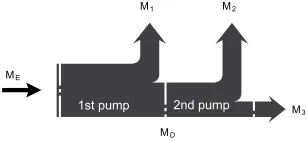
| Eingangsdrehmoment | ME=M1+M2+M3 |
| ME < ME max | |
| Durchtriebsdrehmoment | MD=M2+M3 |
| MD < MD max |
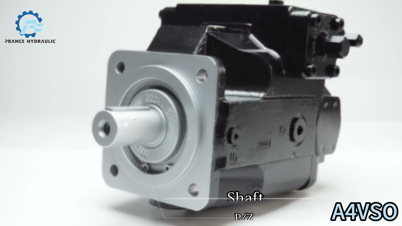
Watch A4VSO Product Video
Related Selection Resources
Request a A4VSO Quotation
Tell us your required configuration, quantity and application.
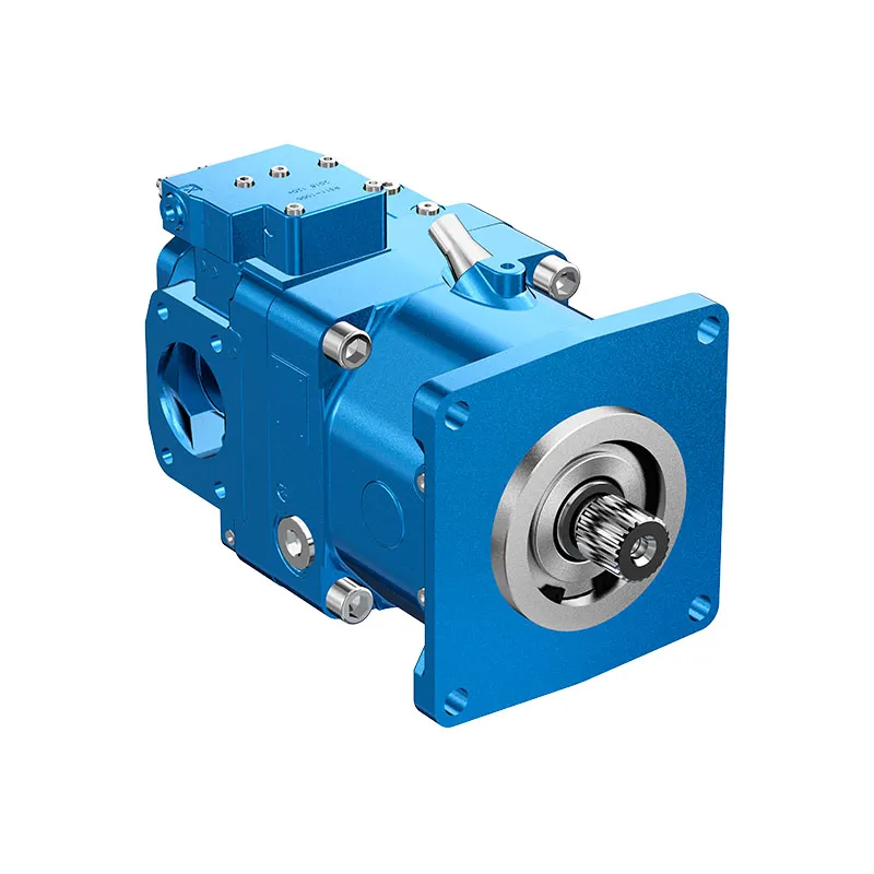
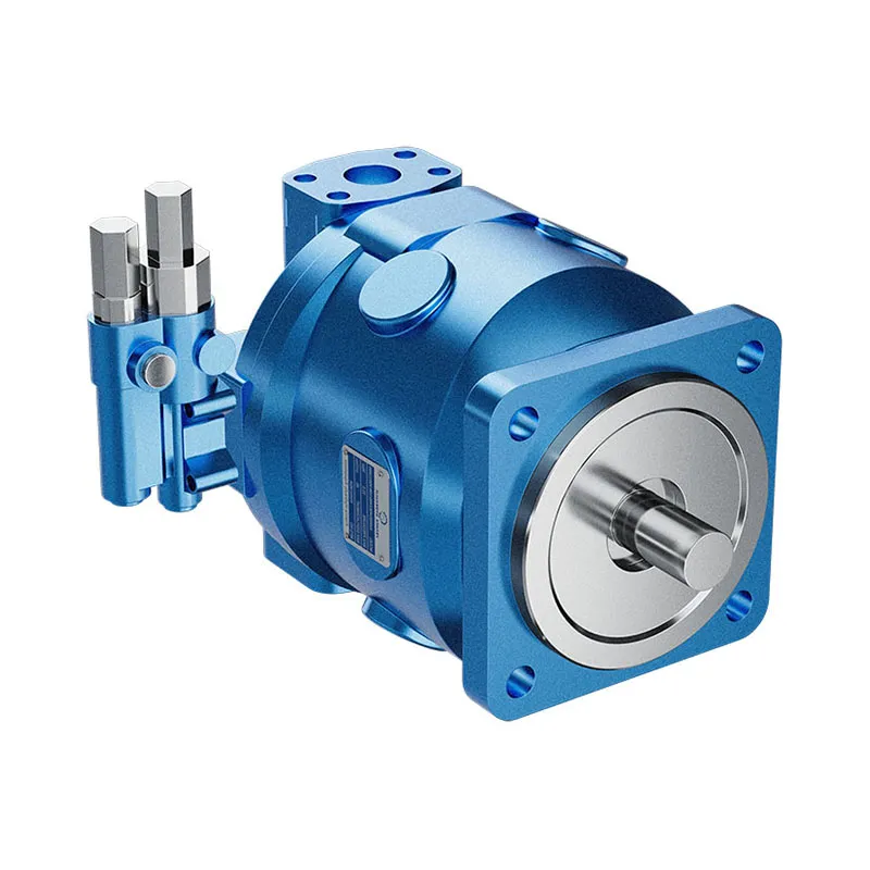
Ähnliche Produkte
Compare related hydraulic pumps and confirm the complete configuration for your application.


BESTELLNUMMER
1. Hydraulikflüssigkeit / Ausführung
| Größe | 40 | 71 | 125 | 180 | 250 | 300 | 355 | 370 | 500 | |
| Mineralöl | √ | √ | √ | √ | √ | √ | √ | √ | △ | |
| HF-Hydraulikflüssigkeit (mit Ausnahme von Skydrol) | √ | √ | √ | √ | √ | √ | √ | √ | △ | E |
| High-Speed-Version | ▲ | ▲ | ▲ | √ | √ | √ | √ | △ | H |
2. Axialkolbeneinheit
| Schrägscheibenbauweise, verstellbar, für industrielle Anwendungen | A4VS |
3. Hilfspumpe (Laufrad)
| Größe | 40 | 71 | 125 | 180 | 250 | 300 | 355 | 370 | 500 | |
| △ | △ | △ | √ | √ | √ | √ | △ | △ | L |
Art des Betriebs
| Pumpe, offener Kreislufe | ○ |
5. Nennweite
| Verdrängung Vg Max (cm3/r) | 40 | 71 | 125 | 180 | 250 | 300 | 355 | 370 | 500 | |
| √ | √ | √ | √ | √ | √ | √ | √ | △ |
6. Steuergerät
| Größe | 40 | 71 | 125 | 180 | 250 | 300 | 355 | 370 | 500 | |
| Druckregelung | DR | √ | √ | √ | √ | √ | √ | √ | √ | △ |
| Ablaufsteuerung | Frankreich | √ | √ | √ | √ | √ | √ | √ | √ | △ |
| Leistungsregelung mit hyperbolischer Kennlinie | LR | √ | √ | √ | √ | √ | √ | √ | √ | △ |
| Manuelle Steuerung | MA | √ | √ | √ | √ | √ | √ | √ | √ | △ |
| Elektromotorregelung | EM | △ | △ | △ | △ | △ | △ | △ | △ | △ |
| Hydraulische Steuerung, wegsabhängig | HW | △ | △ | △ | △ | △ | △ | △ | △ | △ |
| Hydraulische Steuerung, volumenstromabhängig | Hmm | √ | √ | √ | √ | √ | √ | √ | √ | △ |
| Hydrauliksteuerung, mit Servo-/Proportionalventil HS | HS | √ | √ | √ | √ | √ | √ | √ | √ | △ |
| Elektronische Steuerung | EO | √ | √ | √ | √ | √ | √ | √ | √ | △ |
| Hydraulische Steuerung und spannungsbezogen | HD | △ | △ | △ | △ | △ | △ | △ | △ | △ |
| Geschwindigkeitsregelung, die beiden Regler | DS | △ | △ | △ | △ | △ | △ | △ | △ | △ |
7. Serie
| Größe | 40 | 71 | 125 | 180 | 250 | 300 | 355 | 370 | 500 |
| 10er-Serie | √ | √ | ▲ | ▲ | ▲ | ▲ | ▲ | ▲ | ▲ |
| 20er-Serie | ▲ | ▲ | √ | √ | √ | √ | √ | √ | ▲ |
| 30er-Serie | ▲ | ▲ | √ | √ | √ | √ | √ | √ | △ |
Drehrichtung
| Auf das Wellenende gesehen | im Uhrzeigersinn | R |
| gegen den Uhrzeigersinn | L |
9. Robben
| Nitrilkautschuk NBR (DIN 1629) | P |
| Fluorkautschuk FKM (DIN ISO 1629) | V |
10. Wellenende
| Parallele Welle mit Passfeder DIN 6885 | P |
| Passverzahnte Welle DIN 5480 | Z |
√=verfügbar △=in Vorbereitung ▲=nicht verfügbar
11. Befestigungsflansch
| Größe | 40 | 71 | 125 | 180 | 250 | 300 | 355 | 370 | 500 | |
| ISO 04 Bohrung | √ | √ | √ | √ | √ | √ | √ | √ | ▲ | B |
| IS08-Loch | ▲ | ▲ | ▲ | ▲ | ▲ | ▲ | ▲ | ▲ | △ | H |
12. Ölanschluss B & S Position
| 40 | 71 | 125 | 180 | 250 | 300 | 355 | 370 | 500 | ||
| Die Ölanschlüsse B und S befinden sich an der Seite der SAE, im 90°-Winkel, mit festem Gewinde | √ | √ | √ | √ | √ | √ | √ | √ | △ | 13 |
| Sekundärdruck-Ölanschluss B1 liegt gegenüber von Anschluss B. Sie müssen bei der Lieferung mit Flanschen verschlossen werden. | √ | √ | √ | √ | √ | √ | √ | √ | △ | 25 |
Vollständiger Kardanantrieb
| Keine Hilfspumpen, Kein kompletter Wellenantrieb | √ | √ | √ | √ | √ | √ | √ | √ | ||||
| Kompletter Wellenantrieb kann an den Kolben, die Zahnradpumpen oder die Radialkolbenpumpen angeschlossen werden | ||||||||||||
| Flansch | Wellenhülse/Welle | verbindbar | ||||||||||
| ISO 125, 4-Loch | Keilwellenprofil 32x2x30x14x9g | A4VSO/H/G 40 | √ | √ | √ | √ | √ | √ | √ | √ | △ | K33 |
| S0 140, 4-Loch | Passverzahnung 40x2x30x18x9g | A4VSO/H/G 71 | ▲ | √ | √ | √ | √ | √ | √ | √ | △ | K33 |
| S0 160, 4-Loch | Passverzahnung 50x2x30x24x9g | A4VS0/H/G 125 | ▲ | ▲ | √ | √ | √ | √ | √ | √ | △ | K34 |
| ISO 160. 4-Loch | Passverzahnung 50x2x30x24x9g | A4VSO/G 180 | ▲ | ▲ | ▲ | √ | √ | √ | √ | √ | △ | K34 |
| ISO 224, 4-Loch | Kerbwelle 60x2x30x28x9g | A4VSO/H/G 250 | ▲ | ▲ | ▲ | ▲ | √ | √ | √ | √ | △ | K35 |
| ISO 224, 4-Loch | Passverzahnung 70x3x30x22x9g | A4VSO/G 355 | ▲ | ▲ | ▲ | ▲ | ▲ | ▲ | √ | √ | △ | K77 |
| ISO315, 8-Loch | Passverzahnung 80x3x30x25x9g | A4VSO/G 500 | ▲ | ▲ | ▲ | ▲ | ▲ | ▲ | ▲ | ▲ | △ | K43 |
| ISO 80, 2-Loch | Kerbverzahnung 3/4" 19-4(SAE A-B) | A10VSO18 | △ | △ | √ | √ | √ | △ | △ | △ | △ | KB2 |
| S0 100,2-Loch | Keilwelle 7/8" 22-4 (SAE B) | A10VSO28 | √ | √ | √ | √ | √ | √ | √ | √ | △ | KB3 |
| S0 100,2-Loch | Keilwelle 1" 25-4 (SAE B-B) | A10VS045 | ▲ | △ | √ | √ | √ | √ | △ | △ | △ | KB4 |
| ISO 125, 2-Loch | Kerbverzahnung 1 1/4" 32-4(SAE C) | A10VS071 | ▲ | △ | √ | √ | √ | √ | △ | △ | △ | KB5 |
| ISO 125, 2-Loch | Keilwelle 1 1/2" 38-4 (SAE C-C) | A10VS0 100 | ▲ | ▲ | √ | √ | √ | √ | △ | △ | △ | KB6 |
| ISO 180, 4-Loch | Spline1 3/4" 44-4(SAE D) | A10VSO 140 | ▲ | ▲ | ▲ | △ | √ | √ | √ | △ | △ | KB7 |
| 82-2 (SAE A, 2-Loch) | Keilwellenprofil 5/8" 16-4(SAE A) | G2/GC2/GC3-1X | √ | √ | √ | √ | √ | √ | √ | √ | △ | K01 |
| 82-2 (SAE A, 2-Loch) | Spline 3/4" 19-4 (SAE A-B) | A10VSO18 | √ | √ | √ | √ | √ | √ | √ | √ | △ | K52 |
| 101-2 (SAE B, 2-Loch) | Keilwelle 7/8" (SAE B) | G3 | √ | √ | √ | √ | √ | √ | √ | √ | △ | K02 |
| 101-2 (SAE B) | Spline25-4(SAE B-B) | GC4-1X.A10V045 | ▲ | ▲ | √ | √ | √ | √ | √ | √ | △ | K04 |
| 127-2(SAE C) | Spline32-4(SAE C) | A10VO71 | ▲ | ▲ | √ | √ | √ | △ | △ | △ | △ | K07 |
| 101-2 (SAE B) | Spline32-4(SAE C) | GC5-1X | ▲ | ▲ | √ | √ | √ | △ | △ | △ | △ | K06 |
| 127-2(SAE C) | Spline 38-4 (SAE C-C) | GC6-1X, A10VO 100 | ▲ | ▲ | √ | √ | √ | △ | △ | △ | △ | K24 |
| 152-4 (SAE D) | Spline44-4(SAE D) | A10VO 140 | ▲ | ▲ | ▲ | √ | √ | △ | △ | △ | △ | K17 |
| 063, metrisch 4-Loch | Welle mit Passfeder 025 | R4 | √ | √ | √ | √ | √ | △ | △ | △ | △ | K57 |
| 101-2(SAE B) | 22-4 (SAE B) | G4, A10VO 28 | √ | √ | √ | √ | √ | √ | √ | △ | △ | K68 |
| Bandpasswelle, ohne Hülse, ohne Reduzierflansch. | √ | √ | √ | √ | √ | √ | √ | √ | △ | K99 | ||
√=verfügbar △=in Vorbereitung ▲=nicht verfügbar
Technische Daten
Standard-Rotationsgruppenausführung
| Größe | NG | 40 | 71 | 125 | 180 | 250 | 355 | 500 | 750 | 7505) | 1000 | ||
| Geometrische Verschiebung
pro Umdrehung |
VG-Max | cm3 | 40 | 71 | 125 | 180 | 250 | 355 | 500 | 750 | 750 | 1000 | |
| Drehzahl
Maximum1) |
bei VG-Max2) | nnom | U/min | 2600 | 2200 | 1800 | 1800 | 1500 | 1500 | 1320 | 1200 | 1500 | 1000 |
| bei Vg ≤ Vg Max3) | nMax | U/min | 3200 | 2700 | 2200 | 2100 | 1800 | 1700 | 1600 | 1500 | 1500 | 1200 | |
| Fluss | bei nnom und VG-Max | qv | l/min | 104 | 156 | 225 | 324 | 375 | 533 | 660 | 900 | 1125 | 1000 |
| bei 1500 U/min | qv | l/min | 60 | 107 | 186 | 270 | 375 | 533 | 5816) | 7706) | 1125 | - | |
| Macht | Mit nnom, VG-Max
und Δp = 350 bar |
P | kW | 61 | 91 | 131 | 189 | 219 | 311 | 385 | 525 | 656 | 583 |
| bei 1500 U/min | P | kW | 35 | 62 | 109 | 158 | 219 | 311 | 3396) | 4496) | 656 | - | |
| Drehmoment | bei VG-Max
und Δp = 350 bar2) |
MMax | Machs gut | 223 | 395 | 696 | 1002 | 1391 | 1976 | 2783 | 4174 | 4174 | 5565 |
| und Δp = 100 bar2) | M | Machs gut | 64 | 113 | 199 | 286 | 398 | 564 | 795 | 1193 | 1193 | 1590 | |
| Verdrehsteifigkeit von
Antriebswelle |
Wellenende P | c | kNm/rad | 80 | 146 | 260 | 328 | 527 | 800 | 1145 | 1860 | 1860 | 2730 |
| Wellenende Z | c | kNm/rad | 77 | 146 | 263 | 332 | 543 | 770 | 1136 | 1812 | 1812 | 2845 | |
| Trägheitsmoment | JTW | Kgm2 | 0.0049 | 0.0121 | 0.03 | 0.055 | 0.0959 | 0.19 | 0.3325 | 0.66 | 0.66 | 1.20 | |
| Maximale Winkelbeschleunigung4) | α | rad/s2 | 17000 | 11000 | 8000 | 6800 | 4800 | 3600 | 2800 | 2000 | 2000 | 1450 | |
| Fallzahl | V | L | 2 | 2.5 | 5 | 4 | 10 | 8 | 14 | 19 | 22 | 27 | |
| Gewicht (ohne Durchtrieb) ca. | m | kg | 39 | 53 | 88 | 102 | 184 | 207 | 320 | 460 | 490 | 605 | |
Hochgeschwindigkeits-Rotationsgruppenversion
| Größe | NG | 71 | 250 | 355 | 500 | ||
| Geometrisches Fördervolumen pro Umdrehung | VG-Max | cm3 | 71 | 250 | 355 | 500 | |
| Drehzahl
Maximum1) |
bei VG-Max | nnom | U/min | 3000 2)7)8) | 19002) | 17002) | 15002) |
| bei Vg ≤ Vg Max | nMax | U/min | - | 21003) | 19003) | 18003) | |
| Fluss | bei nnom und VG-Max | qv | l/min | 213 7)8) | 475 | 604 | 750 |
| Macht | unter nnom, VG-Max
und Δp = 350 bar |
P | kW | 124 | 277 | 352 | 437 |
| Drehmoment | bei VG-Max
und Δp = 350 bar |
MMax | Machs gut | 395 | 13912) | 19762) | 27832) |
| Verdrehsteifigkeit von
Antriebswelle |
Wellenende P | c | kNm/rad | 146 | 527 | 800 | 1145 |
| Wellenende Z | c | kNm/rad | 146 | 543 | 770 | 1136 | |
| Trägheitsmoment | JTW | Kgm2 | 0.0121 | 0.0959 | 0.19 | 0.3325 | |
| Maximale Winkelbeschleunigung4) | α | rad/s2 | 11000 | 4800 | 3600 | 2800 | |
| Fallzahl | V | L | 2.5 | 10 | 8 | 14 | |
| Gewicht (ohne Durchtrieb) ca. | m | kg | 53 | 184 | 207 | 320 | |
Die Werte gelten:
- auf den optimalen Viskositätsbereich von Ventscheiden = 36 bis 16 mm2/s
- mit Hydraulikflüssigkeit auf Mineralölbasis
2) Die Werte gelten bei absolutem Druck PABS = 1 bar an den Sauganschlüssen.
3) Maximale Drehzahl (Drehzahlgrenze) bei Erhöhung des Einlassdrucks PABS an Saugstutzen und Vg < Vg Max, siehe Abbildung auf Seite 9.
4) Die Daten gelten für Werte zwischen der minimal erforderlichen und der maximal zulässigen Drehzahl. Gültig für äußere Erregung (z. B. Dieselmotor das 2- bis 8-fache der Drehzahl; Gelenkwelle das Zweifache der Drehzahl). Der Grenzwert gilt nur für eine einzelne Pumpe. Die Belastbarkeit der Verbindungsteile muss berücksichtigt werden.
5) mit Speisepumpe (A4VSLO)
6) Bei Vg < VGMax
7) Falls Vg > 30% (je nach Drehzahl, siehe Diagramm "High Speed NG71")
8) Für Ansaugdruck < 1 bar siehe Diagramm Maximale Drehzahl (Drehzahlgrenze) keine Drehzahlsteigerung bei steigendem Eingangsdruck möglich.
Zulässige Höchstgeschwindigkeit (Geschwindigkeitsbegrenzung) (Ps abs = Einlassdruck [bar])
Maximal zulässige Drehzahl bei High Speed Größe 71
Bestimmung der Merkmale
| Fluss | qv=(Vg ∙ n ∙ ηv) / 1000 | l/min |
| Drehmoment | M=(Vg ∙ Δp) / 20 ∙ π ∙ ηhm | Machs gut |
| Macht | P=(2π ∙ M ∙ n)/60000=(qv ∙ Δp)/600 ∙ ηt | kW |
Schlüssel
Vg = Hubvolumen pro Umdrehung in [cm3]
Δp = Differenzdruck [bar]
n = Drehzahl [U/min]
ηv = Volumetrischer Wirkungsgrad
ηhm = Hydraulisch-mechanischer Wirkungsgrad
ηt = Gesamtwirkungsgrad (ηt= ηv*ηhm)
Hinweise
Theoretische Werte, ohne Wirkungsgrad und Toleranzen; Werte gerundet
▶Ein Betrieb oberhalb der Maximalwerte oder unterhalb der Minimalwerte kann zum Funktionsverlust, zu einer verkürzten Lebensdauer oder zur Zerstörung der Axialkolbeneinheit führen. Wir empfehlen, die Belastungen durch Versuche oder Berechnungen / Simulationen zu prüfen und mit den zulässigen Werten zu vergleichen.
▶Bei Riemenantrieben gelten besondere Anforderungen. Bitte kontaktieren Sie uns.
Zulässige Radial- und Axialkräfte der Antriebswellen
| Größe | NG | 40 | 71 | 125 | 180 | 250 | 355 | 500 | 7501) | 1000 | ||
| Radiale Kraft,
Maximum |
|
FQ-max | N | 1000 | 1200 | 1600 | 2000 | 2000 | 2200 | 2500 | 3000 | 3500 |
| Maximale Axialkraft | |
±FAch, Max | N | 600 | 800 | 1000 | 1400 | 1800 | 2000 | 2000 | 2200 | 2200 |
Zulässige Eingangs- und Durchtriebsdrehmomente
| Größe | 40 | 71 | 125 | 180 | 250 | 355 | 500 | 750 | 1000 | |||
| Drehmoment bei VG-Max und Δp = 350 bar1) | MMax | Machs gut | 223 | 365 | 696 | 1002 | 1391 | 1976 | 2783 | 4174 | 5565 | |
| Maximales Eingangsdrehmoment an der Antriebswelle2) | ||||||||||||
| Gespindelte Welle Z | ME max | Machs gut | 446 | 790 | 1392 | 2004 | 2782 | 3952 | 5566 | 8348 | 11130 | |
| Paßfeder P | ME max | Machs gut | 380 | 700 | 1392 | 1400 | 2300 | 3557 | 5200 | 7513 | 9444 | |
| Maximales Durchtriebsdrehmoment | ||||||||||||
| Gespindelte Welle Z | MD Max | Machs gut | 223 | 395 | 696 | 1002 | 1391 | 1976 | 2783 | 4174 | 5565 | |
| Paßfeder P | MD Max | Machs gut | 157 | 305 | 696 | 398 | 909 | 1581 | 2417 | 3339 | 3879 | |
Drehmomentverteilung
| Drehmoment an der 1. Pumpe | M1 |
| Drehmoment an der 2. Pumpe | M2 |
| Drehmoment an der 3. Pumpe | M3 |
| Eingangsdrehmoment | ME=M1+M2+M3 |
| ME < ME max | |
| Durchtriebsdrehmoment | MD=M2+M3 |
| MD < MD max |
1)Effizienz nicht berücksichtigt
2)Für Gelenkwellen ohne Radialkraft
