Wenzhou Prance Hydraulic Equipment Co., Ltd.


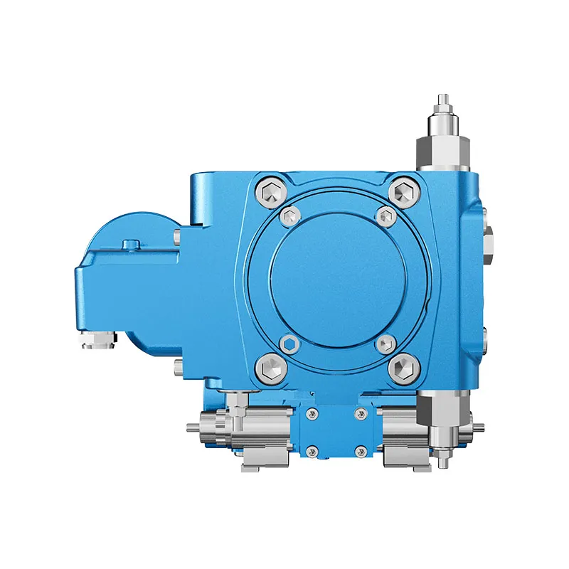
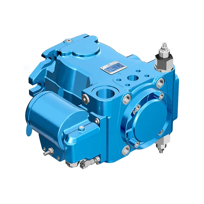
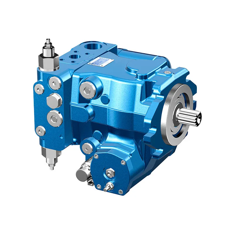
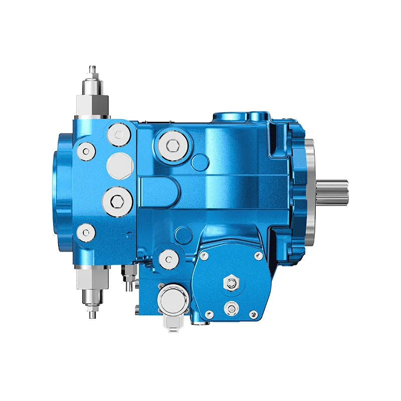
A4VTG Hydrostatic Transmission Piston Pump
The A4VTG variable piston pump is listed for hydraulic transmission duty. Its reversible swashplate flow and auxiliary oil functions must be matched to the motor loop, control arrangement and machine duty cycle.
- Auxiliary boost and pilot supply
- Reversible flow through neutral
- Pressure cut-off and relief functions
- Through-drive option
PRANCE HYDRAULIC · PRODUCT SERIES
A4VTG Hydrostatic Transmission Piston Pump
Axial piston; variable swashplate · Closed-circuit transmission; confirm configuration
The A4VTG variable piston pump is listed for hydraulic transmission duty. Its reversible swashplate flow and auxiliary oil functions must be matched to the motor loop, control arrangement and machine duty cycle.
Model
✓
Request a QuotationTechnische Daten & Datenblatt anzeigenA4VTGAxial piston; variable swashplate
Confirm the complete model and approved specification with Prance Hydraulic. Product-series references alone do not establish interchangeability.
Configuration review · Technical documentation · Product selection
Produktdetails
- Auxiliary boost and pilot supply
- Reversible flow through neutral
- Pressure cut-off and relief functions
- Through-drive option
CATEGORIES: Kolbenpumpe, Verstellpumpe
A4VTG Features & Application
Auxiliary boost and pilot supply
Account for pilot or replenishment demand and the relevant pressure limits. Include filtration and the return or drain route in the circuit review.
Reversible flow through neutral
Review combined drive torque and simultaneous demand, including any additional pump connected to the drive.
Pressure cut-off and relief functions
Keep continuous, intermittent and peak conditions separate. Use the row for the selected size and configuration.
Through-drive option
Review combined drive torque and simultaneous demand, including any additional pump connected to the drive.
A4VTG Specifications
| Series / model | A4VTG |
|---|---|
| Product type | A4VTG Hydrostatic Transmission Piston Pump |
| Design | Axial piston; variable swashplate |
| Circuit / selection | Closed-circuit transmission; confirm configuration |
| Product role | Hydrostatic transmission pump |
| Auxiliary circuit | Confirm boost pressure, pilot supply and filtration requirements |
A4VTG Selection & Configuration
The A4VTG variable piston pump is listed for hydraulic transmission duty. Its reversible swashplate flow and auxiliary oil functions must be matched to the motor loop, control arrangement and machine duty cycle.
Review transmission startup, neutral, reversal and stopping as operating states. Check charge supply, cooling and replenishment during each state, and confirm the exact control and drive interface rather than selecting from displacement alone.
cURL Too many subrequests by single Worker invocation. To configure this limit, refer to https://developers.cloudflare.com/workers/wrangler/configuration/#limits.
cURL Too many subrequests by single Worker invocation. To configure this limit, refer to https://developers.cloudflare.com/workers/wrangler/configuration/#limits.
Hydraulic pumps · Hydraulic motors · Hydraulic valves
Send the MS nameplate, operating requirements and installation drawing for a configuration review before quoting.
- Model review — send the full model code or an existing nameplate photograph.
- Interface matching — confirm shaft, mounting flange, rotation and ports.
- Operating conditions — provide flow, pressure, speed, fluid and duty cycle.
- Documentation — request the relevant product data and drawings for your review.

A4VTG Buying Guide
Use this sequence to prepare the A4VTG configuration for review and quotation.
- Define required flow at the actual drive speed and continuous pressure.
- Identify peak pressure, duration and the work cycle.
- Confirm the selected displacement control and any auxiliary-drive requirement.
- Match rotation viewed from the shaft end, shaft, flange and ports.
- Review inlet conditions, drain routing and the installation envelope.
- Confirm fluid, viscosity, temperature, filtration and seals.
- Approve the complete model, control, drawing, quantity and delivery terms.
Selection, Documentation & Project Support

Selection Support
Learn more →Share your hydraulic circuit, operating point and installation requirements for a configuration discussion.
Flow · Pressure · Speed · Interfaces

Technical Resources
Learn more →Review product documentation, model codes and technical data before finalizing the specification.
Datasheets · Model codes · Drawings

Project Inquiries
Learn more →Send your required model, quantity, application and project requirements to discuss your inquiry.
Product inquiries · Configuration review
Configuration, Quantity & Delivery
Confirm the complete MS code, approved drawing and operating limits. Availability, quantity, documentation and delivery date are confirmed in the quotation.
Discuss Your A4VTG Application
Send the full model code, operating duty, installation details and quantity.
Request a A4VTG QuotationA4VTG Questions Before Ordering
What type of product is the A4VTG?
A4VTG Hydrostatic Transmission Piston Pump. Design: Axial piston; variable swashplate. Closed-circuit transmission; confirm configuration. Confirm the complete order code for the offered version.
Can a similar pump replace the A4VTG?
cURL Too many subrequests by single Worker invocation. To configure this limit, refer to https://developers.cloudflare.com/workers/wrangler/configuration/#limits.
cURL Too many subrequests by single Worker invocation. To configure this limit, refer to https://developers.cloudflare.com/workers/wrangler/configuration/#limits
Define required flow at the actual drive speed and continuous pressure. Identify peak pressure, duration and the work cycle. Attach the nameplate, complete order code, installation drawing and required quantity.
A4VTG Technical Data & Documents
View A4VTG catalog data and operating conditions
cURL Too many subrequests by single Worker invocation. To configure this limit, refer to https://developers.cloudflare.com/workers/wrangler/configuration/#limits.
Technische Daten
Hydraulikflüssigkeit
Before starting project planning, please refer to our data sheets RE 90220 (mineral oil) and RE 90221 (environmentally acceptable hydraulic fluids) for detailed information regarding the choice of hydraulic fluids and application conditions. The A4VTG variable pump is not suitable for operation with HFA, HFB and HFC. If HFD or environmentally acceptable hy-draulic fluids are being used, the limitations regarding technical data and seals must be observed.Please contact us. When ordering, indicate the hydraulic fluid that is to be used.Auswahldiagramm

Einzelheiten zur Auswahl der Hydraulikflüssigkeit
The correct choice of hydraulic fluid requires knowledge of the operating temperature in relation to the ambient temperature: in a closed circuit the circuit temperature. The hydraulic fluid should be chosen so that the operating viscosity in the operating temperature range is within the optimum range (ventscheiden), see shaded area of the selection diagram. We recommended that the higher viscosity class be selected in each case. Example: At an ambient temperature of X °C, an operating temperature of 60 °C is set in the circuit. In the optimum operating viscosity range (ventscheiden.schattierter Bereich), entspricht dies den Viskositätsklassen VG 46 oder VG 68; auszuwählen ist: VG 68.Notiz
The case drain temperature, which is affected by pressure and speed, is always higher than the circuit temperature. At no point of the component may the temperature be higher than115 °C, however. The temperature difference specified below is to be taken into account when determining the viscosity in the bearing. If the above conditions cannot be maintained due to extreme operating parameters, please contact us.Viskosität und Temperatur
| Viskosität [mm2/s] | Temperatur | Kommentar | |
| Speicher | Tmin. ≥ -50 °C | bis zu 12 Monate mit Standard-Werkskonservierung | |
| Tentscheiden = +5 °C bis +20 °C | bis zu 24 Monate mit Langzeit-Werkskonservierung | ||
| Kaltstart1) Permissible tempera- ture difference | VMax=1600 | TSt≥ -40 °C | t≤3 min, ohne Last (p≤50 bar), n ≤ 1000 rpm |
| ΔT≤25K | zwischen Axialkolbeneinheit und Hydraulikflüssigkeit | ||
| Aufwärmphase | v<1600to400 | T = -40 °C bis -25 °C | bei Pnom,0,5·nnom und t ≤ 15 Min. |
| Operating phase Temperature difference | ΔT = ca. 5 K | Die Temperatur des Hydrauliköls im Lager ist (je nach Druck und Drehzahl) ca. 5 K höher als die des Gehäusesickeröls an Anschluss T. | |
| Dauerbetrieb | v=400 to 10 Ventscheiden=16 bis 36 | T = -25 °C bis +90 °C | keine Einschränkung innerhalb der zulässigen Daten |
| Kurzzeitbetrieb | Vmin.=<10 bis 5 | TMax = +115 °C | t < 3 min, p < 0,3 · Pnom |
| Wellendichtring FKM1) | T ≤ +115 °C | siehe Seite 5 | |
Filtration der Hydraulikflüssigkeit
Filtration improves the cleanliness level of the hydraulic fluid,which, in turn, increases the service life of the axial piston unit. To ensure the functional reliability of the axial piston unit, a gravimetric evaluation is necessary for the hydraulic fluid to determine the amount of contamination by solid matter and to determine the cleanliness level according to ISO 4406. A cleanliness level of at least 20/18/15 is to be maintained. Depending on the system and the application, for the A4VTG,we recommend Filter cartridges β20 > 100. With an increasing differential pressure at the filter cartridges,the B-value must not deteriorate. At very high hydraulic fluid temperatures (90 °C to maximum 115 °C), a cleanliness level of at least 19/17/14 according to ISO 4406 is necessary. If the above classes cannot be achieved, please contact us. For notes on filtration types, see page 16.Wellendichtring
Permissible pressure loading The service life of the shaft seal ring is affected by the speed of the pump and the case drain pressure. It is recommended that the average, continuous case drain pressure 3 bar absolute at operating temperature not be exceeded (maximum permissible case drain pressure 6 bar absolute at reduced speed,see diagram). Short-term (t <0.1 s) pressure spikes of up to10 bar absolute are permitted. The service life of the shaft seal ring decreases with an increase in the frequency of pressure spikes. The case pressure must be equal to or greater than the external pressure on the shaft seal ring.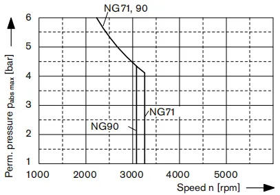
Temperaturbereich
Der FKM-Wellendichtring kann für Leöl- bzw. Gehäusedrücktemperaturen von -25 °C bis +115 °C verwendet werden.Notiz
For application cases below -25 °C, an NBR shaft seal ring is necessary (permissible temperature range: -40 °C to +90 °C). State NBR shaft seal ring in plain text when ordering. Please contact us.Betriebsdruckbereich
Pressure at service line port A or B Nominal pressure pnom———– 400 bar absolute Maximum pressure PMax———– 450 bar absolute Single operating period————– 10s Total operating period————– 300h Minimum pressure (high-pressure side)———— 25 bar Minimum pressure (inlet)————–10 bar(boost pressure setting must be higher depending on system) Rate of pressure change RA max———— 9000 bar/s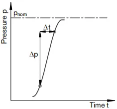
Kraftstoffförderpumpe
cURL Too many subrequests by single Worker invocation. To configure this limit, refer to https://developers.cloudflare.com/workers/wrangler/configuration/#limitss min (v ≤ 30 mm2cURL Too many subrequests by single Worker invocation. To configure this limit, refer to https://developers.cloudflare.com/workers/wrangler/configuration/#limitss maxcURL Too many subrequests by single Worker invocation. To configure this limit, refer to https://developers.cloudflare.com/workers/wrangler/configuration/#limitsSp cURL Too many subrequests by single Worker invocation. To configure this limit, refer to https://developers.cloudflare.com/workers/wrangler/configuration/#limitsSp nomcURL Too many subrequests by single Worker invocation. To configure this limit, refer to https://developers.cloudflare.com/workers/wrangler/configuration/#limitsSp maxcURL Too many subrequests by single Worker invocation. To configure this limit, refer to https://developers.cloudflare.com/workers/wrangler/configuration/#limitsSmin. t cURL Too many subrequests by single Worker invocation. To configure this limit, refer to https://developers.cloudflare.com/workers/wrangler/configuration/#limitsDefinition
Nenndruck Pnom cURL Too many subrequests by single Worker invocation. To configure this limit, refer to https://developers.cloudflare.com/workers/wrangler/configuration/#limitsMax cURL Too many subrequests by single Worker invocation. To configure this limit, refer to https://developers.cloudflare.com/workers/wrangler/configuration/#limitsA Maximal zulässiger Druckaufbau- und Druckabbaukoeffizient bei einer Druckänderung über den gesamten Druckbereich.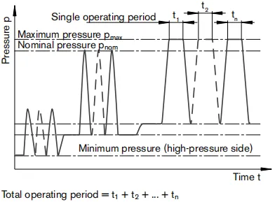
Wertetabelle (theoretische Werte, ohne Wirkungsgrade und Toleranzen; Werte gerundet)
| Größe | NG | 71 | 90 | |||
| Verschiebung | Verstellpumpe | Vg Max | cm3 | 70 | 90 | |
| Hilfspumpe (bei p = 20 bar) | Vg Sp | cm3 | 20.5 | 27 | ||
| Geschwindigkeit | bei VG-Max | nnom | U/min | 3300 | 3050 | |
| Minimum | nmin. | U/min | 500 | 500 | ||
| Drehmoment1) | bei VG-Max und | Δp = 400 bar | TMax | Machs gut | 452 | 573 |
| Δp = 100 bar | T | Machs gut | 113 | 143 | ||
| Verdrehsteifigkeit | Antriebswelle V8 | c | Nm/rad | 120900 | – | |
| Antriebswelle V9 | c | Nm/rad | – | 150896 | ||
| Trägheitsmoment der Drehgruppe | JGR | Kgm2 | 0.0097 | 0.0149 | ||
| Maximale Winkelbeschleunigung2) | α | rad/s2 | 21000 | 18000 | ||
| Füllmenge | V | L | 1.3 | 1.2 | ||
| Masse ca. (ohne Durchtrieb) | m | kg | 51 | 53 | ||
Notiz
Ein Betrieb oberhalb der Maximalwerte oder unterhalb der Minimalwerte kann zum Funktionsverlust, zu einer verkürzten Lebensdauer oder zur Zerstörung der Axialkolbeneinheit führen. Wir empfehlen, die Belastungen durch Experimente oder Berechnungen/Simulationen sowie durch einen Vergleich mit den zulässigen Werten zu überprüfen.Bestimmung der Betriebskennlinien
Zulässige Radial- und Axialbelastung der Antriebswelle
| Größe | NG | 71 | 90 | ||
| Antriebswelle | in | 1 3/8 | 1 1/2 | ||
| Radial force maximum at distance a (from shaft collar) |  |
Fq Max a | N mm | 5600 24 | 7100 24 |
| Axialkraft-Maximum | 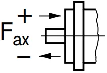 |
+FAch, Max | N | 4242 | 4330 |
| -FAch, Max | N | 2758 | 2670 | ||
Notiz
Special requirements apply in the case of belt drives. Please contact us. Force-transfer direction of the permissible axial force: + FAxt Max=Increase in service life of bearings – FAxt Max= Verkürzung der Lebensdauer von Lagern (vermeiden)Zulässige Eingangs- und Durchtriebsdrehmomente
| Größe | NG | 71 | 90 | |||
| Input torque at drive shaft, maximum2) | V8 | Machs gut | TEmax | Machs gut | 970 | – |
| V9 | Machs gut | TEmax | Machs gut | – | 1305 | |
| Maximales Durchtriebsdrehmoment | TDMax | Machs gut | 250 | 250 | ||
Related Selection Resources
Request a A4VTG Quotation
Tell us your required configuration, quantity and application.
Ähnliche Produkte
Compare related hydraulic pumps and confirm the complete configuration for your application.


Bestellnummer für Standardprogramm
| A4VT | G | / | 33 | M | N | C4 | F | A | S | |||||||||
| 01 | 02 | 03 | 04 | 05 | 06 | 07 | 08 | 09 | 10 | 11 | 12 | 13 | 14 | 15 | 16 | 17 | 18 |
Axialkolbeneinheit
| 01 | Taumelscheibenausführung, variabel, Nenndruck 400 bar, Maximaldruck 450 bar, mobile Betonmischer | A4VT |
Betriebsart
| 02 | Pumpe, geschlossener Kreislauf | G |
Größe
| 03 | Verdrängung Vg Max in cm3 | 071 | 090 |
Steuergerät
| 071 | 090 | ||||
| 04 | Proportionale hydraulische Steuerung, mechanischer Servo, Sechskantwelle mit Hebel nach hinten | ● | ● | Hausaufgabe 11) | |
| Elektrische Proportionalregelung,
mit Notbetätigung und Rückstellfeder |
U=12VDC | ● | ● | EP3 | |
| U = 24 VDC | ● | ● | EP4 | ||
Magnetstecker2)
| 071 | 090 | |||
| 05 | Ohne | ● | ● | 0 |
| DEUTSCH-Steckverbinder, 2-polig – ohne Entstördiode | ● | ● | P | |
Hilfsfunktionen
| 071 | 090 | |||
| 06 | Ohne | ● | ● | 0 |
| Mit mechanischem Hubbegrenzer, von außen einstellbar | ● | ● | M | |
| Mit den Anschlüssen X3, X4 für den Hubkammerdruck | ● | ● | T | |
| Mit mechanischem Hubbegrenzer und Anschlüssen X3, X4 | ● | ● | B | |
Serie
| 07 | Serie 3, Index 3 | 33 |
Version des Ports und der Befestigungsgewinde
| 08 | Metrisch | M |
Drehrichtung
| 09 | Von der Antriebswelle aus gesehen | im Uhrzeigersinn | R |
| gegen den Uhrzeigersinn | L |
Robben
| 10 | NBR (Nitrilkautschuk), Wellendichtring aus FKM (Fluororobkautschuk) | N |
Montageflansch
| 11 | SAEJ744, 127-4 | C4 |
Antriebswelle
| 071 | 090 | |||||
| 12 | Kerbwelle
ANSIB92.1a-1976 |
1 3/8 Zoll 21T 16/32DP | ohne Kupplungsflansch | ● | - | V8 |
| mit Kupplungsflansch | ● | - | C8 | |||
| 1 1/2 in 23T 16/32DP | ohne Kupplungsflansch | - | ● | V9 | ||
| mit Kupplungsflansch | - | ● | C9 | |||
Servicetüranschlüsse
| 071 | 090 | |||||
| 13 | SAE-Flanschanschluss
A und B auf derselben Seite |
links | Sauganschluss S unten | ○ | ○ | 1 |
| rechts | Sauganschluss S oben | ● | ● | 2 | ||
• = verfügbar ○ = auf Anfrage - = nicht verfügbar
1) Die Einbaulage des Hebels ist bei Lieferung nicht festgelegt und muss vom Kunden angepasst werden.
2) Die Anschlüsse für andere elektrische Komponenten können davon abweichen.
Kraftstoffförderpumpe
| 14 | Mit integrierter Vorförderpumpe | F |
Durchfahrt
| 15 | SAE-J744-Flansch | Kupplung für Keilwelle1) | |||||||
| Montagevariante | |||||||||
| Durchmesser | Symbolbezeichnung | Durchmesser | Bezeichnung | 071 | 090 | ||||
| Ohne | ● | ● | 0000 | ||||||
| 82-2 |  |
A2 | 5/8 in 9T | 16/32DP | S2 | ● | ● | A2S2 | |
| 101-2 | |
B2 | 7/8 in 13T | 16/32DP | S4 | ● | ● | B2S4 | |
Hochdruckventile
| 16 | Mit direkt gesteuertem Hochdruck-Entlastungsventil | A |
Filtrationsverstärkungsschaltung
| 17 | Filtration in der Vorrats- oder Hilfspumpen-Saugleitung | S |
Standard- / Sonderversion
| 12 | Standardversion | -0 | |
| kombiniert mit Anbauteil oder Anbaupumpe | -K | ||
| Sonderversion | -S | ||
| kombiniert mit Anbauteil oder Anbaupumpe | -T |
Notiz
Die Kurzbezeichnung X bezieht sich auf eine Sonderausführung, die nicht im Bestelltitel enthalten ist.
• = verfügbar ○ = auf Anfrage - = nicht verfügbar
3) Kupplung für Passfahnwelle nach ANSI B92.1a-1976
Technische Daten
Hydraulikflüssigkeit
Vor Beginn der Projektplanung beachten Sie bitte unsere Datenblätter RE 90220 (Mineralöl) und RE 90221 (umweltverträgliche Hydraulikflüssigkeiten) für detaillierte Informationen bezüglich der Auswahl der Hydraulikflüssigkeiten und der Einsatzbedingungen.
Die Verstellpumpe A4VTG ist nicht für den Betrieb mit HFA, HFB und HFC geeignet. Bei Verwendung von HFD oder umweltfreundlichen Hydraulikflüssigkeiten müssen die Einschränkungen bezüglich der technischen Daten und Dichtungen beachtet werden. Bitte kontaktieren Sie uns.
Geben Sie bei der Bestellung an, welche Hydraulikflüssigkeit verwendet werden soll.
Auswahldiagramm
Einzelheiten zur Auswahl der Hydraulikflüssigkeit
Die korrekte Auswahl der Hydraulikflüssigkeit erfordert die Kenntnis der Betriebstemperatur in Relation zur Umgebungstemperatur: in einem geschlossenen Kreislauf die Kreislauftemperatur.
Die Hydraulikflüssigkeit sollte so ausgewählt werden, dass die Betriebsviskosität im Betriebstemperaturbereich im optimalen Bereich liegt (ventscheiden), siehe schattierter Bereich des Auswahldiagramms. Wir empfehlen, in jedem Fall die höhere Viskositätsklasse zu wählen.
Beispiel: Bei einer Umgebungstemperatur von X °C stellt sich im Kreislauf eine Betriebstemperatur von 60 °C ein. Im optimalen Betriebsviskositätsbereich (ventscheiden.schattierter Bereich), entspricht dies den Viskositätsklassen VG 46 oder VG 68; auszuwählen ist: VG 68.
Notiz
Die Lecköl-Temperatur, die durch Druck und Drehzahl beeinflusst wird, ist immer höher als die Kreislauftemperatur. An keinem Punkt der Komponente darf die Temperatur jedoch höher als 115 °C sein. Die unten angegebene Temperaturdifferenz ist bei der Bestimmung der Viskosität im Lager zu berücksichtigen.
Falls die vorgenannten Bedingungen aufgrund extremer Betriebsparameter nicht eingehalten werden können, setzen Sie sich bitte mit uns in Verbindung.
Viskosität und Temperatur
| Viskosität [mm2/s] | Temperatur | Kommentar | |
| Speicher | Tmin. ≥ -50 °C | bis zu 12 Monate mit Standard-Werkskonservierung | |
| Tentscheiden = +5 °C bis +20 °C | bis zu 24 Monate mit Langzeit-Werkskonservierung | ||
| Kaltstart1)
Zulässige Tempera- Temperaturdifferenz |
VMax=1600 | TSt≥ -40 °C | t≤3 min, ohne Last (p≤50 bar), n ≤ 1000 rpm |
| ΔT≤25K | zwischen Axialkolbeneinheit und Hydraulikflüssigkeit | ||
| Aufwärmphase | v<1600to400 | T = -40 °C bis -25 °C | bei Pnom,0,5·nnom und t ≤ 15 Min. |
| Betriebsphase
Temperatur Unterschied |
ΔT = ca. 5 K | Die Temperatur des Hydrauliköls im Lager ist (je nach Druck und Drehzahl) ca. 5 K höher als die des Gehäusesickeröls an Anschluss T. | |
| Dauerbetrieb | v=400 auf 10
Ventscheiden=16 bis 36 |
T = -25 °C bis +90 °C | keine Einschränkung innerhalb der zulässigen Daten |
| Kurzzeitbetrieb | Vmin.=<10 bis 5 | TMax = +115 °C | t < 3 min, p < 0,3 · Pnom |
| Wellendichtring FKM1) | T ≤ +115 °C | siehe Seite 5 | |
Bei Temperaturen unter -25 °C ist ein NBR-Wellendichtring erforderlich
(zulässiger Temperaturbereich: -40 °C bis +90 °C)
Filtration der Hydraulikflüssigkeit
Die Filtration verbessert den Reinheitsgrad der Hydraulikflüssigkeit, was wiederum die Lebensdauer der Axialkolbeneinheit erhöht.
Zur Sicherstellung der Funktionssicherheit der Axialkolbeneinheit ist eine gravimetrische Auswertung der Hydraulikflüssigkeit erforderlich, um den Feststoffverschmutzungsgrad zu bestimmen und die Sauberkeitsklasse gemäß ISO 4406 zu ermitteln. Dabei ist eine Sauberkeitsklasse von mindestens 20/18/15 einzuhalten.
Je nach System und Anwendung empfehlen wir für den A4VTG
Filterkerzen β20 > 100.
Bei einem ansteigenden Differenzdruck an den Filterpatronen darf sich der B-Wert nicht verschlechtern.
Bei sehr hohen Hydraulikflüssigkeitstemperaturen (90 °C bis maximal 115 °C) ist eine Reinheitsklasse von mindestens 19/17/14 gemäß ISO 4406 erforderlich.
Wenn die oben genannten Klassen nicht erreicht werden können, kontaktieren Sie uns bitte.
Hinweise zu den Filtrationsarten finden Sie auf Seite 16.
Wellendichtring
Zulässige Druckbelastung
Die Lebensdauer des Wellendichtrings wird durch die Drehzahl der Pumpe und den Lecköldruck im Gehäuse beeinflusst. Es wird empfohlen, den durchschnittlichen, kontinuierlichen Lecköldruck von 3 bar absolut bei Betriebstemperatur nicht zu überschreiten (maximal zulässiger Lecköldruck 6 bar absolut bei reduzierter Drehzahl, siehe Diagramm). Kurzfristige (t < 0,1 s) Druckspitzen von bis zu 10 bar absolut sind zulässig. Die Lebensdauer des Wellendichtrings nimmt mit zunehmender Häufigkeit von Druckspitzen ab.
Der Gehäusedruck muss gleich oder größer sein als der äußere Druck auf den Wellendichtring.
Temperaturbereich
Der FKM-Wellendichtring kann für Leöl- bzw. Gehäusedrücktemperaturen von -25 °C bis +115 °C verwendet werden.
Notiz
Für Anwendungsfälle unter -25 °C ist ein NBR-Wellendichtring erforderlich (zulässiger Temperaturbereich: -40 °C bis +90 °C).
Standard-NBR-Wellendichtring bei der Bestellung im Klartext angeben.
Bitte kontaktieren Sie uns.
Betriebsdruckbereich
Druck am Arbeitsanschluss A oder B
Nenndruck pnom----------- 400 bar absolut
Maximaler Druck PMax----------- 450 bar absolut
Einzelne Betriebsdauer-------------- 10s
Gesamte Betriebsdauer-------------- 300h
Mindestdruck (Hochdruckseite)------------ 25 bar
Mindestdruck (Einlass)--------------10 bar (Ladedruckeinstellung muss je nach System höher sein)
Druckänderungsrate RA max------------ 9000 bar/s
Kraftstoffförderpumpe
Druck am Sauganschluss S
Dauer ps min (v ≤ 30 mm2/s)--------------≥ 0,8 bar absolut
bei Kaltstarts, kurzzeitig (t < 3 min) -------------≥ 0,5 bar absolut
Maximum ps max----------------≤5 bar absolut
Standardeinstellung pSp (bei n = 1500 U/min)------------ 22 bar
Nenndruck pSp nom--------------- 30 bar
Maximaler Druck pSp max--------------- 0 bar
Steuerdruck
Um die Funktion der Steuerung zu gewährleisten, ist je nach Drehzahl und Betriebsdruck der folgende Steuerdruck erforderlich (Messpunkt, Anschluss Ps):
Für Steuerungen EP und HW
Mindeststeuerdruck PSmin. t (bei n = 1500 U/min) --- 22 bar
Definition
Nenndruck Pnom
Der Nenndruck entspricht dem maximalen Auslegungsdruck.
Maximaler Druck pMax
Der Maximaldruck entspricht dem maximalen Betriebsdruck innerhalb der einzelnen Betriebsperiode. Die Summe der einzelnen Betriebsperioden darf die gesamte Betriebsperiode nicht überschreiten.
Mindestdruck (Hochdruckseite)
Mindestdruck auf der Hochdruckseite (A oder B), der erforderlich ist, um Schäden an der Axialkolbeneinheit zu verhindern.
Mindestdruck (Einlass)
Mindestdruck am Einlass (A oder B), der erforderlich ist, um Schäden an der Axialkolbeneinheit zu vermeiden.
Druckänderungsrate RA
Maximal zulässiger Druckaufbau- und Druckabbaukoeffizient bei einer Druckänderung über den gesamten Druckbereich.
Wertetabelle (theoretische Werte, ohne Wirkungsgrade und Toleranzen; Werte gerundet)
| Größe | NG | 71 | 90 | |||
| Verschiebung | Verstellpumpe | Vg Max | cm3 | 70 | 90 | |
| Hilfspumpe (bei p = 20 bar) | Vg Sp | cm3 | 20.5 | 27 | ||
| Geschwindigkeit | bei VG-Max | nnom | U/min | 3300 | 3050 | |
| Minimum | nmin. | U/min | 500 | 500 | ||
| Fluss | bei nnom H und Vg Max | qv max | l/min | 234 | 275 | |
| Macht1) | bei nnom H, VG-Max | Δp = 400 bar | PMax | kW | 156 | 183 |
| Drehmoment1) | bei VG-Max und | Δp = 400 bar | TMax | Machs gut | 452 | 573 |
| Δp = 100 bar | T | Machs gut | 113 | 143 | ||
| Verdrehsteifigkeit | Antriebswelle V8 | c | Nm/rad | 120900 | - | |
| Antriebswelle V9 | c | Nm/rad | - | 150896 | ||
| Trägheitsmoment der Drehgruppe | JGR | Kgm2 | 0.0097 | 0.0149 | ||
| Maximale Winkelbeschleunigung2) | α | rad/s2 | 21000 | 18000 | ||
| Füllmenge | V | L | 1.3 | 1.2 | ||
| Masse ca. (ohne Durchtrieb) | m | kg | 51 | 53 | ||
1) Ohne Förderpumpe
2) Der Geltungsbereich liegt zwischen der mindestens erforderlichen und der maximal zulässigen Geschwindigkeit.
Dies gilt für externe Anregungen (z. B. Motor mit 2- bis 8-facher Drehfrequenz, Kardanwelle mit der 2-fachen Drehfrequenz).
Der Grenzwert gilt nur für eine einzelne Pumpe.
Die Tragfähigkeit der Verbindungsteile muss berücksichtigt werden.
Notiz
Ein Betrieb oberhalb der Maximalwerte oder unterhalb der Minimalwerte kann zum Funktionsverlust, zu einer verkürzten Lebensdauer oder zur Zerstörung der Axialkolbeneinheit führen. Wir empfehlen, die Belastungen durch Experimente oder Berechnungen/Simulationen sowie durch einen Vergleich mit den zulässigen Werten zu überprüfen.
Bestimmung der Betriebskennlinien
| Fluss | qv=(Vg ∙ n ∙ ηv) / 1000 | l/min |
| Drehmoment | T=(Vg ∙ Δp) /(20 ∙ π ∙ ηhm) | Machs gut |
| Macht | P=(2π ∙ T ∙ n)/60000=(qv ∙ Δp)/(600 ∙ ηt) | kW |
Vg = Hubvolumen pro Umdrehung in cm³3
Δp = Differenzdruck in bar
n = Drehzahl in U/min
ηv = Volumetrischer Wirkungsgrad
ηmh Mechanisch-hydraulischer Wirkungsgrad
ηt = Gesamtwirkungsgrad (ηt= ηv* ηmh)
Zulässige Radial- und Axialbelastung der Antriebswelle
| Größe | NG | 71 | 90 | ||
| Antriebswelle | in | 1 3/8 | 1 1/2 | ||
| Radiale Kraft (Maximum)
in der Entfernung a (von Stellring) |
|
Fq Max
a |
N
mm |
5600
24 |
7100
24 |
| Axialkraft-Maximum | |
+FAch, Max | N | 4242 | 4330 |
| -FAch, Max | N | 2758 | 2670 | ||
Notiz
Für Riemenantriebe gelten besondere Anforderungen. Bitte kontaktieren Sie uns.
Kraftübertragungsrichtung der zulässigen Axialkraft:
+ FAxt MaxErhöhung der Lebensdauer von Lagern
- FAxt Max= Verkürzung der Lebensdauer von Lagern (vermeiden)
Zulässige Eingangs- und Durchtriebsdrehmomente
| Größe | NG | 71 | 90 | |||
| Drehmoment bei VG-Max und Δp = 400 bar)1) | TMax | Machs gut | 452 | 573 | ||
| Eingangsdrehmoment
an der Antriebswelle, maximal2) |
V8 | Machs gut | TEmax | Machs gut | 970 | - |
| V9 | Machs gut | TEmax | Machs gut | - | 1305 | |
| Maximales Durchtriebsdrehmoment | TDMax | Machs gut | 250 | 250 | ||
1) Effizienz nicht berücksichtigt
2) Für Gelenkwellen ohne Radialkraft