Wenzhou Prance Hydraulic Equipment Co., Ltd.

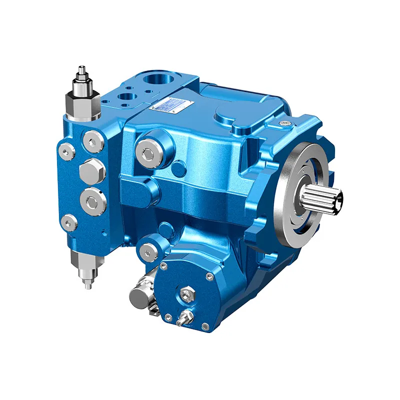
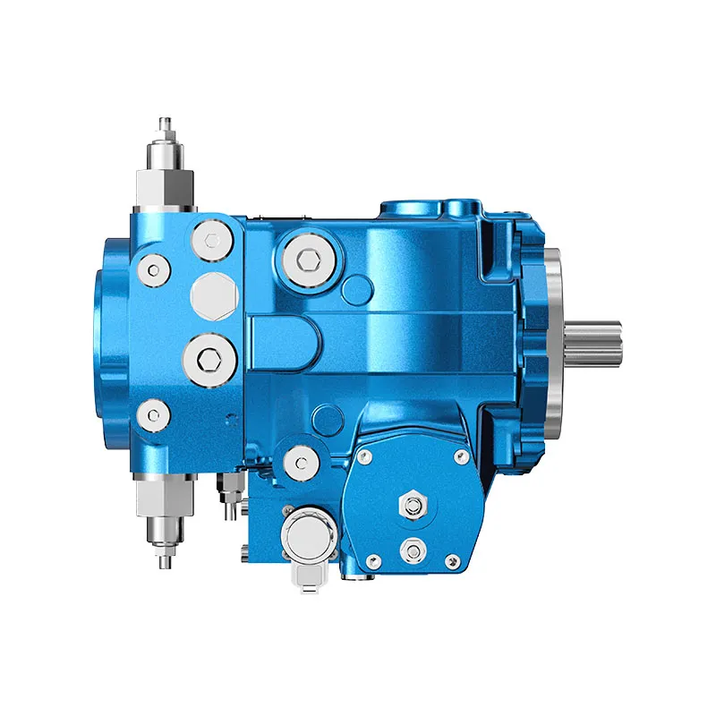

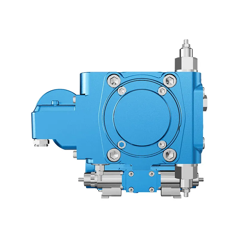
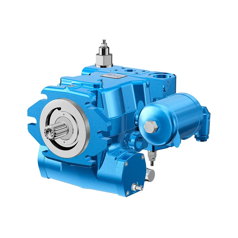
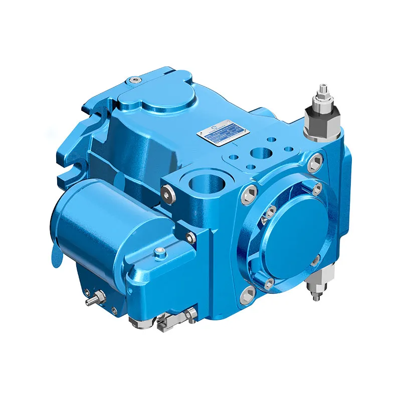
Hydraulic Transmission Piston Pump A4VTG
1.Integrated auxliay pump for boost and piot oilsupply.
2.Flow direcion changes smoothy when the swashplate is moved through the neutral postion
3.High-pressure relief valves with integated boost function.
4.With adjustable pressure cut-off as standard
5.Boost-pressure relief valve
6.Through drive for mounting of further pumps up to same nominal size
Descripción detallada
This hydraulic pump is designed with multiple practical functions to ensure stable and efficient operation in various hydraulic systems. It is equipped with an integrated auxiliary pump dedicated to providing stable boost and pilot oil supply, which guarantees sufficient oil pressure for the system’s control components and effectively prevents cavitation. When the swashplate moves through the neutral position, the pump’s flow direction changes smoothly without obvious pressure fluctuations or mechanical impact, reducing internal wear and prolonging service life. It is configured with high-pressure relief valves with integrated boost function and a dedicated boost-pressure relief valve, which jointly protect the system from overpressure damage and maintain stable boost pressure. As a standard configuration, it comes with an adjustable pressure cut-off function, allowing users to flexibly set the cut-off pressure according to actual working needs. Additionally, it features a through drive design that enables the mounting of further pumps up to the same nominal size, expanding the system’s hydraulic output capacity and enhancing application versatility.
Selección y solicitud de cotización
Esta serie de productos debe seleccionarse en función del circuito hidráulico aprobado. Confirme el caudal o desplazamiento requerido, la presión continua y de punta, la velocidad de accionamiento, el tipo de control, el fluido y la interfaz de instalación antes de la selección final.
Información que debe incluir en su RFQ
- Desplazamiento o caudal requerido a la velocidad de operación
- Presión del sistema continua y máxima
- Velocidad de accionamiento, requisito de control y tipo de circuito
- Brida de montaje, eje, puertos, requisitos de fluido y filtración
Recursos relacionados
Ordering code for standard program
| A4VT | G | / | 33 | M | N | C4 | F | A | S | |||||||||
| 01 | 02 | 03 | 04 | 05 | 06 | 07 | 08 | 09 | 10 | 11 | 12 | 13 | 14 | 15 | 16 | 17 | 18 |
Unidad de pistones axiales
| 01 | Swashplate design, variable, nominal pressure 400 bar, maximum pressure 450 bar, mobile concrete mixers | A4VT |
Modo de operación
| 02 | Bomba, circuito cerrado | G |
Tamaño
| 03 | Displacement Vg madrex en cm3 | 071 | 090 |
Dispositivo de control
| 071 | 090 | ||||
| 04 | Proportional control hydraulic, mechanical servo, hexagon shaft with lever to the rear | ● | ● | HW11) | |
| Proportional control electric,
with emergency actuation and spring return |
U=12VDC | ● | ● | EP3 | |
| U=24 VDC | ● | ● | EP4 | ||
Conector para solenoides2)
| 071 | 090 | |||
| 05 | Without | ● | ● | 0 |
| DEUTSCH - molded connector, 2-pin - without suppressor diode | ● | ● | P | |
Auxiliary functions
| 071 | 090 | |||
| 06 | Without | ● | ● | 0 |
| With mechanical stroke limiter, externally adjustable | ● | ● | M | |
| With ports X3, X4 for stroking chamber pressure | ● | ● | T | |
| With mechanical stroke limiter and ports X3, X4 | ● | ● | B | |
Series
| 07 | Series 3, Index 3 | 33 |
Version of port and fixing threads
| 08 | Metric | M |
Sentido de giro
| 09 | Viewed from drive shaft | en el sentido de las agujas del reloj | R |
| anti-clockwise | L |
Focas
| 10 | NBR (caucho de nitrilo), anillo de sello de eje en FKM (caucho fluorado) | N |
Brida de montaje
| 11 | SAEJ744, 127-4 | C4 |
Árbol de transmisión
| 071 | 090 | |||||
| 12 | Eje ranurado
ANSIB92.1a-1976 |
1 3/8 in 21T 16/32DP | without coupling flange | ● | - | V8 |
| with coupling flange | ● | - | C8 | |||
| 1 1/2 in 23T 16/32DP | without coupling flange | - | ● | V9 | ||
| with coupling flange | - | ● | C9 | |||
Puertos de las líneas de servicio
| 071 | 090 | |||||
| 13 | SAE flange port
A and B on same side |
left | Suction port S at bottom | ○ | ○ | 1 |
| right | Suction port S at top | ● | ● | 2 | ||
•= disponible ○= bajo petición -= no disponible
1)Mounting position of the lever not specified on delivery, to be aligned by the customer
2) Connectors for other electric components can deviate.
Bomba de refuerzo
| 14 | With integrated boost pump | F |
A través de la unidad
| 15 | Brida SAE J744 | Coupling for splined shaft1) | |||||||
| Mounting variant | |||||||||
| Diámetro | Symbol Designation | Diámetro | Designation | 071 | 090 | ||||
| Without | ● | ● | 0000 | ||||||
| 82-2 |  |
A2 | 5/8 in 9T | 16/32DP | S2 | ● | ● | A2S2 | |
| 101-2 | |
B2 | 7/8 in 13T | 16/32DP | S4 | ● | ● | B2S4 | |
High-pressure valves
| 16 | With high-pressure relief valve, direct controlled | A |
Filtration boost circuit
| 17 | Filtración en la línea de succión de la bomba de refuerzo | S |
Standard / special version
| 12 | Versión estándar | -0 | |
| combined with attachment part or attachment pump | -K | ||
| Special version | -S | ||
| combined with attachment part or attachment pump | -T |
Note
Short designation X refers to a special version not covered by the ordering code.
•= disponible ○= bajo petición -= no disponible
3) Coupling for splined shaft acc. ANSI B92.1a-1976
Datos técnicos
Hydraulic fluid
Before starting project planning, please refer to our data sheets RE 90220 (mineral oil) and RE 90221 (environmentally acceptable hydraulic fluids) for detailed information regarding the choice of hydraulic fluids and application conditions.
The A4VTG variable pump is not suitable for operation with HFA, HFB and HFC. If HFD or environmentally acceptable hy-draulic fluids are being used, the limitations regarding technical data and seals must be observed.Please contact us.
When ordering, indicate the hydraulic fluid that is to be used.
Selection diagram

Details regarding the choice of hydraulic fluid
The correct choice of hydraulic fluid requires knowledge of the operating temperature in relation to the ambient temperature: in a closed circuit the circuit temperature.
The hydraulic fluid should be chosen so that the operating viscosity in the operating temperature range is within the optimum range (velegir), see shaded area of the selection diagram. We recommended that the higher viscosity class be selected in each case.
Example: At an ambient temperature of X °C, an operating temperature of 60 °C is set in the circuit. In the optimum operating viscosity range (velegir.shaded area), this corresponds to the viscosity classes VG 46 or VG 68; to be selected: VG 68.
Note
The case drain temperature, which is affected by pressure and speed, is always higher than the circuit temperature. At no point of the component may the temperature be higher than115 °C, however. The temperature difference specified below is to be taken into account when determining the viscosity in the bearing.
If the above conditions cannot be maintained due to extreme operating parameters, please contact us.
Viscosity and temperature
| Viscosity [mm2/s] | Temperature | Comment | |
| Storage | Tmin ≥ -50 °C | up to 12 months with standard factory conservation | |
| Telegir = +5 °C to +20 °C | up to 24 months with long-term factory conservation | ||
| (Cold) start-up1)
Permissible tempera- ture difference |
Vmáx=1600 | TSt≥ -40°C | t≤3 min, without load (p≤50 bar), n ≤ 1000 rpm |
| ΔT≤25K | between axial piston unit and hydraulic fluid | ||
| Warm-up phase | v<1600to400 | T=-40 °C to-25°C | at PNombre,0.5·nNombre and t ≤ 15 min |
| Operating phase
Temperature difference |
ΔT=approx.5 K | The temperature of the hydraulic fluid in the bearing is (depending on pressure and speed) approx. 5 K higher than that of the case drain fluid at port T. | |
| Continuous operation | v=400 to 10
Velegir=16 to 36 |
T=-25°C to +90 °C | no restriction within the permissible data |
| Short-term operation | Vmin=<10to5 | Tmáx = +115 °C | t<3 min,p<0.3·PNombre |
| Shaft seal ring FKM1) | T≤ +115°C | see page 5 | |
1)At temperatures below -25 °C, an NBR shaft seal ring is required
(permissible temperature range: -40 °C to +90 °C)
Filtration of the hydraulic fluid
Filtration improves the cleanliness level of the hydraulic fluid,which, in turn, increases the service life of the axial piston unit.
To ensure the functional reliability of the axial piston unit, a gravimetric evaluation is necessary for the hydraulic fluid to determine the amount of contamination by solid matter and to determine the cleanliness level according to ISO 4406. A cleanliness level of at least 20/18/15 is to be maintained.
Depending on the system and the application, for the A4VTG,we recommend
Filter cartridges β20 > 100.
With an increasing differential pressure at the filter cartridges,the B-value must not deteriorate.
At very high hydraulic fluid temperatures (90 °C to maximum 115 °C), a cleanliness level of at least 19/17/14 according to ISO 4406 is necessary.
If the above classes cannot be achieved, please contact us.
For notes on filtration types, see page 16.
Shaft seal ring
Permissible pressure loading
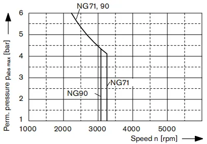
The service life of the shaft seal ring is affected by the speed of the pump and the case drain pressure. It is recommended that the average, continuous case drain pressure 3 bar absolute at operating temperature not be exceeded (maximum permissible case drain pressure 6 bar absolute at reduced speed,see diagram). Short-term (t <0.1 s) pressure spikes of up to10 bar absolute are permitted. The service life of the shaft seal ring decreases with an increase in the frequency of pressure spikes.
The case pressure must be equal to or greater than the external pressure on the shaft seal ring.
Temperature range
The FKM shaft seal ring may be used for case drain temperatures from-25 °C to +115 °C.
Note
For application cases below -25 °C, an NBR shaft seal ring is necessary (permissible temperature range: -40 °C to +90 °C).
State NBR shaft seal ring in plain text when ordering.
Please contact us.
Operating pressure range
Pressure at service line port A or B
Nominal pressure pNombre----------- 400 bar absolute
Maximum pressure Pmáx----------- 450 bar absolute
Single operating period-------------- 10s
Total operating period-------------- 300h
Minimum pressure (high-pressure side)------------ 25 bar
Minimum pressure (inlet)--------------10 bar(boost pressure setting must be higher depending on system)
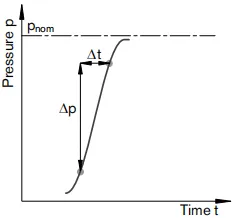
Rate of pressure change RA max------------ 9000 bar/s
Bomba de refuerzo
Pressure at suction port S
Duration ps min (v ≤ 30 mm2/s)--------------≥ 0.8 bar absolute
at cold starts, short-term (t <3 min) -------------≥ 0.5 bar absolute
Maximum ps max----------------≤5 bar absolute
Standard adjustment pSp (at n= 1500 rpm)------------ 22 bar
Nominal pressure pSp Nombre--------------- 30 bar
Maximum pressure pSp max--------------- 0 bar
Control pressure
To ensure the function of the control, the following control pressure is required depending on the speed and operating pressure (measurement point, port Ps):
For controls EP and HW
Minimum control pressure PSt min (at n = 1500 rpm)--- 22 bar
Definition
Presión nominal PNombre
The nominal pressure corresponds to the maximum design pressure.
Maximum pressure pmáx
The maximum pressure corresponds the maximum operating pressure within the single operating period. The sum of the single operating period must not exceed the total operating period.
Minimum pressure (high-pressure side)
Minimum pressure on the high-pressure side (A or B) that is required in order to prevent damage to the axial piston unit.
Minimum pressure (inlet)
Minimum pressure in inlet (A or B) that is required in order to prevent damage to the axial piston unit.
Rate of pressure change RA
Maximum permissible rate of pressure build-up and pressure reduction during a pressure change over the entire pressure range.
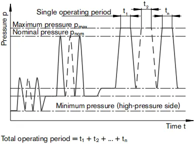
Table of values (theoretical values, without efficiency levels and tolerances; values rounded)
| Tamaño | NG | 71 | 90 | |||
| Desplazamiento | variable pump | Vg máx | cm3 | 70 | 90 | |
| boost pump (at p = 20 bar) | Vg Sp | cm3 | 20.5 | 27 | ||
| Speed | at VG máximo | nNombre | rpm | 3300 | 3050 | |
| minimum | nmin | rpm | 500 | 500 | ||
| Flujo | at nNombre H y Vg máx | qv max | l/min | 234 | 275 | |
| Poder1) | at nNombre H, VG máximo | Δp = 400 bar | Pmáx | kW | 156 | 183 |
| Par de torsión1) | at VG máximo and | Δp = 400 bar | Tmáx | Nm | 452 | 573 |
| Δp = 100 bar | T | Nm | 113 | 143 | ||
| Rotary stiffness | drive shaft V8 | c | Nm/rad | 120900 | - | |
| drive shaft V9 | c | Nm/rad | - | 150896 | ||
| Momento de inercia para el grupo rotativo | JGR | Kgm2 | 0.0097 | 0.0149 | ||
| Aceleración angular máxima2) | α | rad/s2 | 21000 | 18000 | ||
| Filling capacity | V | L | 1.3 | 1.2 | ||
| Mass approx. (without through drive) | m | kg | 51 | 53 | ||
1)Without boost pump
2) The area of validity lies between the minimum required and maximum permissible speed.
It applies for external stimuli (e. g. engine 2 to 8 times rotary frequency, cardan shaft twice the rotary frequency).
The limit value applies for a single pump only.
The load capacity of the connection parts must be considered.
Note
Operation above the maximum values or below the minimum values may result in a loss of function, a reduced service life or in the destruction of the axial piston unit. We recommend testing the loads by means of experiment or calculation/simulation and comparison with the permissible values.
Determinación de las características de funcionamiento
| Flujo | qv=(Vg ∙ n ∙ ηv) / 1000 | l/min |
| Par de torsión | T=(Vg ∙ Δp) /(20 ∙ π ∙ ηhm) | Nm |
| Poder | P=(2π ∙ T ∙ n)/60000=(qv ∙ Δp)/(600 ∙ ηt) | kW |
Vg = Displacement per revolution in cm3
Δp = Differential pressure in bar
n = Speed in rpm
ηv = Volumetric efficiency
ηMh = Mechanical-hydraulic efficiency
ηt = Overall efficiency (ηt= ηv* ηMh)
Permissible radial and axial loading on drive shaft
| Tamaño | NG | 71 | 90 | ||
| Árbol de transmisión | in | 1 3/8 | 1 1/2 | ||
| Radial force maximum
at distance a (from shaft collar) |
 |
Fq máx
a |
N
mm |
5600
24 |
7100
24 |
| Axial force maximum | 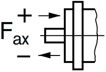 |
+Fax max | N | 4242 | 4330 |
| -Fax max | N | 2758 | 2670 | ||
Note
Special requirements apply in the case of belt drives. Please contact us.
Force-transfer direction of the permissible axial force:
+ Fhacha máx=Increase in service life of bearings
- Fhacha máx=Reduction in service life of bearings (avoid)
Permissible input and through-drive torques
| Tamaño | NG | 71 | 90 | |||
| Torque at VG máximo and Δp= 400 bar)1) | Tmáx | Nm | 452 | 573 | ||
| Input torque
at drive shaft, maximum2) |
V8 | Nm | TEmax | Nm | 970 | - |
| V9 | Nm | TEmax | Nm | - | 1305 | |
| Maximum through-drive torque | TDmáx | Nm | 250 | 250 | ||
1)Efficiency not considered
2) For drive shafts with no radial force