Wenzhou Prance Hydraulic Equipment Co., Ltd.

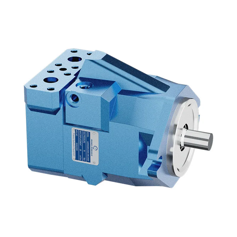
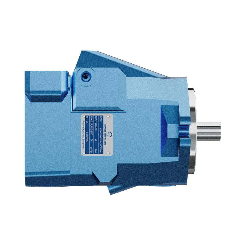
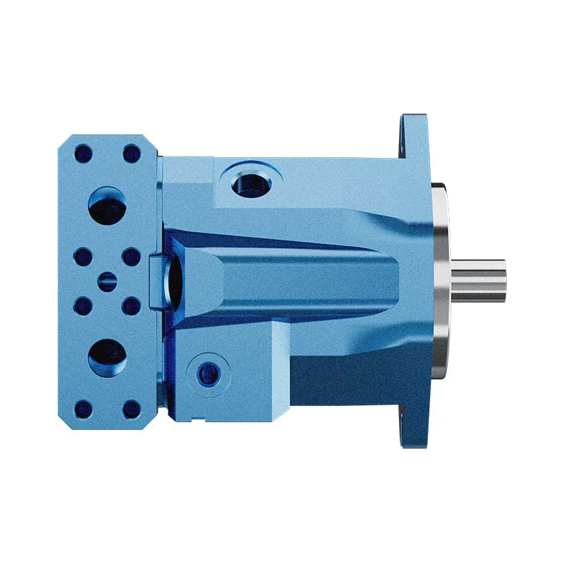
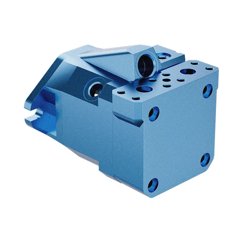
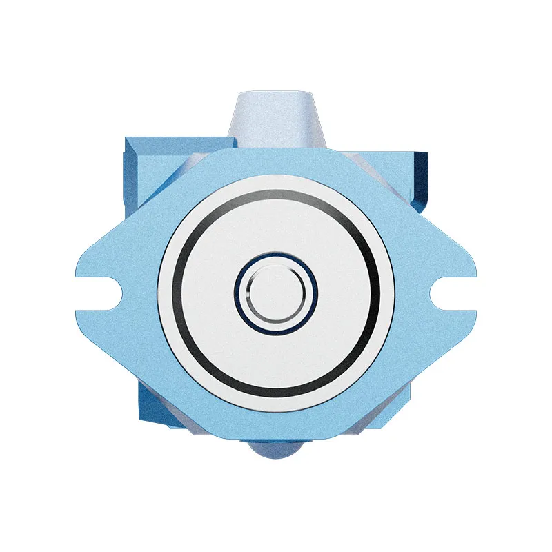
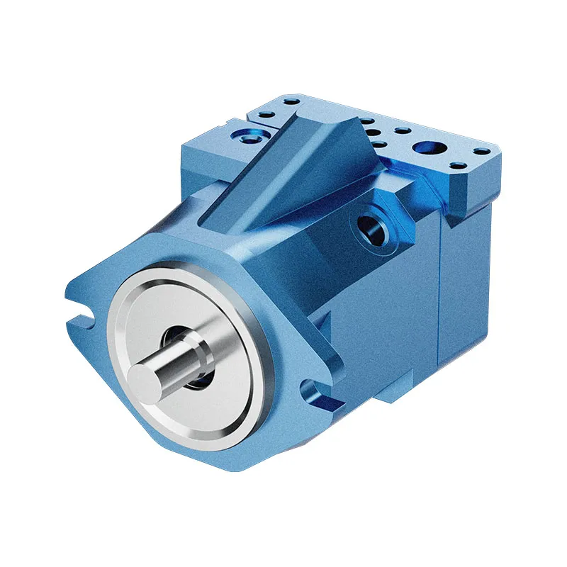
Variable Displacement Piston Motor A10VM
1.Output speed is proportional to input flow rate and inversely proportional to motor displacement
2.Output torque increases proportionally with pressure differential across high/low
3.pressure sides and increased displacement
4.Heavy-duty bearings ensure extended service life
5.Reliable A10 drive technology
6.A10VM features SAE 2-pin mounting flange
Descripción detallada
The A10VM motor features a clear operational relationship: its output speed is proportional to the input flow rate and inversely proportional to the motor displacement. This means that as the input flow increases, the output speed rises accordingly, while a larger displacement leads to a lower speed, allowing for flexible adjustment to match diverse working condition requirements. Its output torque is closely related to pressure and displacement, increasing proportionally with the pressure differential between the high and low pressure sides, as well as with increased displacement, ensuring strong power output to drive heavy loads stably. Equipped with heavy-duty bearings, the motor is designed to withstand high loads and frequent operation, effectively reducing wear and tear during long-term use, thus ensuring an extended service life and reducing maintenance frequency and costs. It adopts reliable A10 drive technology, which has been verified by practical applications to deliver stable performance, strong anti-interference ability, and ensure smooth and reliable operation of the motor even in complex working environments. Additionally, the A10VM is equipped with an SAE 2-pin mounting flange, which conforms to international standards, facilitating easy installation and compatibility with various hydraulic systems, enhancing its versatility and applicability in different scenarios.
Selección y solicitud de cotización
This motor series should be selected from the required torque, speed and duty cycle. Confirm displacement, working pressure, case-drain arrangement where applicable, mounting interface and fluid conditions before final selection.
Información que debe incluir en su RFQ
- Required torque and speed at working pressure
- Preferred displacement or calculated displacement
- Mounting flange, shaft and port orientation
- Duty cycle, fluid, temperature and operating environment
Recursos relacionados
Ordering code for standard program
| A10V | M | / | 52 | W | – | V | C | ||||||||
| 01 | 02 | 03 | 04 | 05 | 06 | 07 | 08 | 09 | 10 | 11 | 12 | 13 | 14 |
Unidad de pistones axiales
| 01 | Swash plate design, variable, nominal pressure 280 bar, maximum pressure 350 bar | A10V |
Operating Mode
| 02 | Motor, open and closed circuit | M |
Tamaño (NG)
| 03 | Displacement VG máximo en cm3 | 028 | 045 | 063 | 085 |
Dispositivos de control
| 028 | 045 | 063 | 085 | ||||||
| 04 | Two point control |
Directly operated, external control supply, without pilot valve | ● | ● | ● | ● | DG | ||
| Hydraulically operated | Stroking time | without | ● | ● | ● | ○ | HZ | ||
| Electricaly with solenoid valve | orifice | with | ● | ● | ● | ○ | HZ6 | ||
| Electricaly with solenoid valve | Stroking time | without | ● | ● | ● | ● | EZ1 | ||
| control voltage 12V | orifice | with | ● | ● | ● | ● | EZ6 | ||
| Electricaly with solenoid valve | Stroking time | without | ● | ● | ● | ○ | EZ2 | ||
| control voltage 24V | orifice | with | ● | ● | ● | ○ | EZ7 | ||
Series
| 05 | Series 5, Index 2 | 52 |
Sentido de giro
| 06 | Viewed on shaft end Bi-directional | W |
Minimum displacement
| 028 | 045 | 063 | 085 | ||||
| 07 | Vg min (in cm3) steplessly adjustable | from/to | 8/28 | 12/25 | 16/38 | 22/50 | 1 |
| Adjustment state in clear text | from/to | – | 26/45 | 40/62 | 48/85 | 2 | |
Focas
| 08 | FKM (flour-rubber) | V |
Árbol de transmisión
| 028 | 045 | 063 | 085 | |||
| 09 | Splined shaft, ANSI B92.1 a-1976, for higher drive torque | ● | ● | ● | ● | R |
| Splined shaft, ANSI B92.1 a-1976, for reduced drive torque | – | ● | ● | ● | W | |
Brida de montaje
| 10 | SAE J744 2-bolt | C |
Ports for service lines
| 11 | SAE flanges, at side-same side, metric fixing screws | ● | ● | ● | ● | 10N00 | |||||
| SAE flanges at rear, metric fixing screws | ○ | ● | ○ | ○ | 11N00 | ||||||
| Threaded ports on side, same side, metric thread | ● | ● | ● | ○ | 16N00 | ||||||
Valves
| 12 | Without valves | ● | ● | ● | ● | 0 | |||||
| Integrated flushing valve, only with side ports (10N00 and 16N00) | ● | ● | ● | ● | 7 | ||||||
Speed pickup
| 13 | Without speed pickup | ● | ● | ● | ● | – | ||||
| Prepared for inductive type of speed pickup ID R | ● | ● | ● | ○ | D | |||||
Conector para solenoides
| 14 | HIRSCHMANN - connector — without suppressor diod | ▲ | ▲ | ▲ | ▲ | H | |||||
| DEUTSCH - connector, molded, 2-pin —without suppressor diod | ● | ● | ● | ● | P | ||||||
•=available ○=in preparation — =not available ▲=not for new projects
| A10V | E | / | 52 | W | – | V | F | ||||||||
| 01 | 02 | 03 | 04 | 05 | 06 | 07 | 08 | 09 | 10 | 11 | 12 | 13 | 14 |
Unidad de pistones axiales
| 01 | Swash plate design, variable, nominal pressure 280 bar, maximum pressure 350 bar | A10v | |||||||
Modo de operación
| 02 | Motor, plug in type, open and closed circuit | E | |||
Tamaño (NG)
| 03 | Displacement VG máximo en cm3 | 028 | 045 | 063 |
Dispositivos de control
| 028 | 045 | 063 | ||||||
| 04 | Two point control |
Directly operated, external control supply, without pilot valve | ● | ● | ○ | DG | ||
| Hydraulically | Stroking time | without | ● | ● | ● | HZ | ||
| orifice | with | ● | ● | ● | HZ6 | |||
| Electricaly with solenoid valve | Stroking time | without | ● | ● | ● | EZ1 | ||
| control voltage 12V | orifice | with | ● | ● | ● | EZ6 | ||
| Electricaly with solenoid valve | Stroking time | without | ● | ● | ● | EZ2 | ||
| control voltage 24V | orifice | with | ● | ● | ● | EZ7 | ||
Series
| 05 | Series 5, Index 2 | 52 |
Sentido de giro
| 06 | Viewed on shaft end Bi-directional | W | ||||
Minimum displacement
| 028 | 045 | 063 | ||||
| 07 | Vg min (in cm3) stepples adjustable | from/to | 10/28 | 12/25 | 16/38 | 1 |
| Adjustment please state in clear text | from/to | – | 26/45 | 40/62 | 2 | |
Focas
| 08 | FKM (flour-rubber) | V |
Árbol de transmisión
| 028 | 045 | 063 | |||||||
| 09 | Splined shaft, ANSI B92.1 a-1976, for higher drive torque | ● | ● | ● | R | ||||
| Splined shaft, ANSI B92.1 a-1976, for reduced drive torque | – | ● | ● | W | |||||
Brida de montaje
| 10 | Special 2-bolt | F |
Ports for service line
| 11 | SAE flanges at side-same side, metric fixing screws | ● | ● | ● | 10N00 | ||||
| SAE flanges at rear, metric fixing screws | ○ | ● | ○ | 11N00 | |||||
| Threaded ports on side, same side, metric thread | ● | ● | ● | 16N00 | |||||
Valves
| 12 | Without valves | ● | ● | ● | 0 | |||||
| Integrated flushing valve, only with side ports (10N00 and 16N00) | ● | ● | ● | 7 | ||||||
Speed pickup
| 13 | Without speed pickup | ● | ● | ● | – | ||||
| Prepared for inductive type of speed pickup ID R | ○ | ● | ○ | D | |||||
Conector para solenoides
| 14 | HIRSCHMANN - connector—without suppressor diod | ▲ | ▲ | ▲ | H | |||||
| DEUTSCH - connector, molded, 2-pin—without suppressor diod | ● | ● | ● | P | ||||||
•=available ○=in preparation — =not available ▲=not for new projects
Datos técnicos
Fluid
Prior to project design please see our data sheets RE 90220(mineral oil), RE 90221 (ecologically acceptable fluids) and RE90223(HF-fluids) for detailed information on fluids and application conditions.
When operating on ecologically acceptable fluids, limitations to the technical data may be necessary.
Please contact us and state the fluid used in clear text when ordering.
Operating viscosity range
For optimum efficiency and service life we recommend an ope-rating viscosity (at operating temperature) in the range
νelegir = opt. operating viscosity 16...36 mm2/s
referred to circuit temperature in closed circuits or tank temperature in open circuits.
The following limits are valid for extreme operating conditions:
Vmin=5 mm2/s (closed circuit)
Vmin=10 mm2/s (open circuit)
briefly (t≤ 1 min) at max. permissible temperature of 115℃.
Please note, that the max. fluid temperature of 115℃ may also not be exceeded in certain areas (for instance bearing area)
The temperature in the bearing area is approx. 5 K higher than the average fluid temperature.
νmáx=1600 mm2/s
briefly (t≤ 1 min)
on cold start (tmin = -25℃, p≤30 bar, n≤1000 rpm).
At temperatures between -25 ℃ and -40 ℃ special measures may be required for certain installation positions. Please consult us for further information
For detailed information on operation at very low temperatures see RE 90300-03-B.
Notes on the selection of the hydraulic fluid
In order to select the correct fluid, it is necessary to know the operating temperature in the tank (open circuit), circuit temperature (closed circuits), in relation to the ambient temperature.
The fluid should be selected, so that within the operating temperature range, the viscosity lies within the optimum range(νelegir), see shaded section of the selection diagram. We recommend to select the higher viscosity grade in each case.
Example: at an ambient temperature of X ℃ the operating temperature in the tank is 60℃.In the optimum viscosity range(νelegir; shaded area) this corresponds to viscosity grades VG 46 resp. VG 68; select VG 68.
Important: The leakage fluid (case drain fluid) temperature is influenced by pressure and motor speed and is always higher than the tank temperature. However, at no point in the circuit may the temperature exceed 115 ℃.
If it is not possible to comply with the above conditions because of extreme operating parameters or high ambient temperatures please consult us
Filtration of fluid
The finer the filtration the better the achieved cleanliness of the fluid and the longer the life of the axial piston unit.
To ensure a reliable functioning of the axial piston unit, a minimum cleanliness of
20/18/15 to ISO 4406 is necessary.
At very high fluid temperatures (90℃ to max. 115℃) the minimum cleanliness has to be at least
19/17/14 to ISO 4406.
If above cleanliness classes cannot be met please consult us.
Operating pressure range
Pressure at port A or B
(Pressure data to DIN 24312)
| Nominal pressure pN | 280 bar 1) |
| Maximum pressure Pmáx | 350 bar |
| With motors connected in series please consult us. | |
Presión de drenaje de la caja
| Max. permissible pressure at leakage port L | |
| Pabdominales max operation as a motor in open circuit | 4 bar abs |
| Pabdominales max operation as a motor in closed circuit | 4 bar abs |
| Pabdominales max motor/pump operation in open circuit | 2 bar abs |
Sentido de giro
| Direction of rotation, viewed on shaft end | |||||
| en el sentido de las agujas del reloj | en sentido contrario a las agujas del reloj | ||||
| B to A | A to B | ||||
Adjustment of displacement
The minimum displacement is steplessly adjustable within the range of the screw lengths
1 or 2 (see ordering code).
Please state minimum displacement in clear text when ordering.
Selection diagram
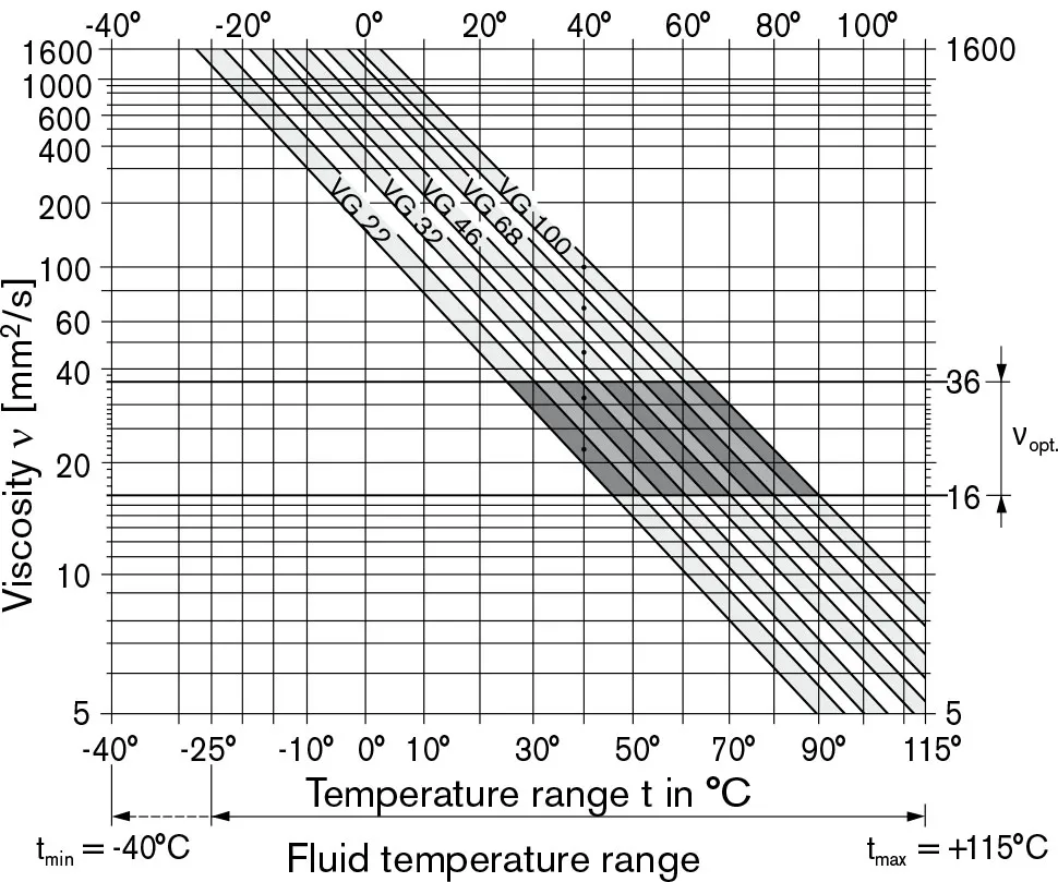
Table of values(theoretical values, without efficiency levels and tolerances; values rounded)
| Tamaño | 28 | 45 | 63 | 85 | |||
| Desplazamiento | VG máximo | cm3 | 28 | 45 | 62 | 87 | |
| Vg min | cm3 | 8 (VM)/10(VE) | 12 | 16 | 22 | ||
| Speed1) | 4700 | 4000 | 3300 | 3100 | |||
| max. at VG máximo | n0 max | min-1 | |||||
| max. at Vg min | n0 max zul | min-1 | 5400 | 4600 | 3900 | 3560 | |
| Min.speed in cont. operation | n0 min | min-1 | 250 | 250 | 250 | 250 | |
| Inlet flow | 131,6 | 180 | 205 | 270 | |||
| bei n0 max y VG máximo | qv0 máx | L/min | |||||
| Torque constant2) at VG máximo | TK | Nm/bar | 0,445 | 0,716 | 1,002 | 1,35 | |
| Par de torsión | 125 | 200 | 276 | 387 | |||
| at VG máximo | PN= 280 bar | Tmáx | Nm | ||||
| Actual starting torque | 92 | 149 | 205 | 253 | |||
| at n=0 min-1 | PN = 280 bar | T | Nm ca. | ||||
| Rotary stiffness | Shaft R | c | Nm/rad | 26000 | 41000 | 69400 | 152900 |
| Shaft W | c | Nm/rad | 19800 | 34400 | 54000 | 117900 | |
| Mass moment of inertia (about output shaft) | J | kgm2 | 0,0017 | 0,0033 | 0,0056 | 0,012 | |
| Filling volume | V | L | 0,6 | 0,7 | 0,8 | 1,0 | |
| Weight approx. | m | kg | 14 | 18 | 26 | 34 | |
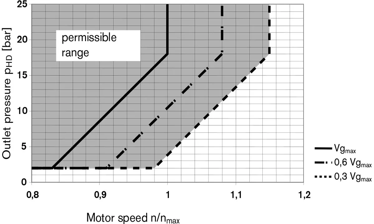
1) At maximal speed in closed circuit operation make sure that motor outlet pressure is at least≥18 bar.
2) In open circuit Δp 280bar at Pboostpress. 2bar
In closed circuit Δp 260bar at Pboostpress. 20bar
Minimum required outlet pressure (low pressure) at port A (B)
depending on motor speed
Calculating size
| Flujo | qv=(Vg∙n)/(1000∙ηv) | [L/min] | Vg=Displacement per rev. in cm3 Δp=Differential pressure in bar n=speed in rpm ηv=Volumetric efficiency ηMh=Mechanical-hydraulic efficiency ηt=Total efficiency (ηt = ηv ∙ηMh) TK=Torque constant |
| Par de torsión | T=(1,59∙Vg∙ Δp∙ηMh)/100 | [Nm] | |
| or | T=Tk∙ Δp∙ηMh | ||
| Output power | P=(2π∙T∙n)/60000=(qv∙Δp∙ηt)/600 | [kW] | |
| Output speed | n=(qv∙1000∙ηv)/Vg | [min-1] | |
Permissible radial and axial forces on drive shaft
| Tamaño | 28 | 45 | 63 | 85 | ||||
| Max. radial force | 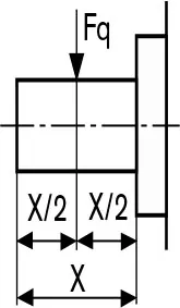 |
at X/2 | Fq max | N | 1200 | 1500 | 1700 | 2000 |
| Max. axial force | 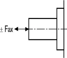 |
Fhacha | N | 1000 | 1500 | 2000 | 3000 | |
