Wenzhou Prance Hydraulic Equipment Co., Ltd.

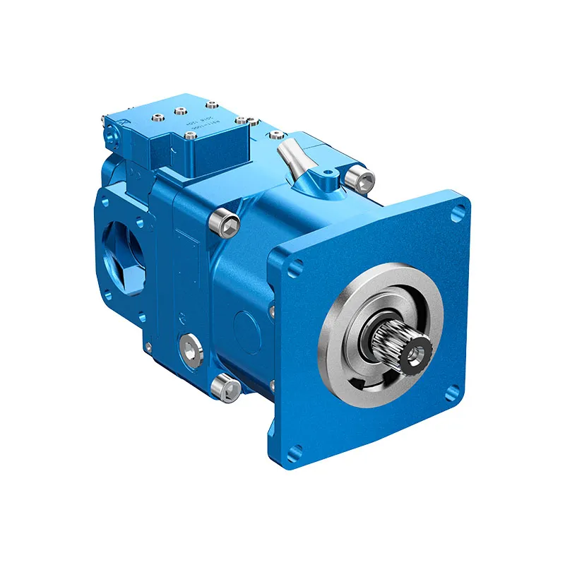
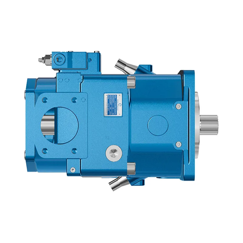


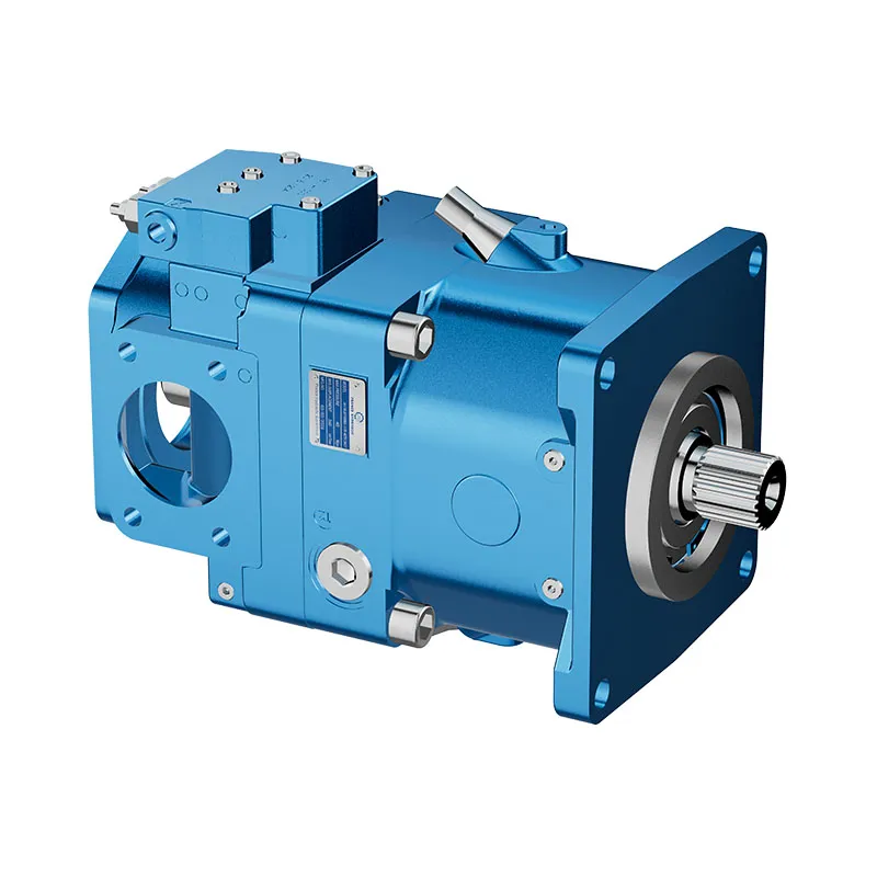
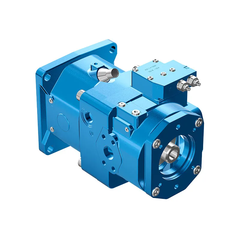
Verstellbare Axialkolbenpumpe A11VO
1. Verstellpumpe in Axialkolbenbauweise, Schrägscheibenbauweise, für hydrostatische Antriebe im Offenen Kreis
2. In erster Linie für die Verwendung in mobilen Anwendungen konzipieren
3. Pumpenbetrieb entweder selbstansaugend, mit Behälterfüllung oder Ladepumpe
Ein umfassendes Sortiment an variablen Einheiten ist für verschiedene Steuerungsfunktionen verfügbar.
Die Leistung kann von außen geregelt werden, selbst wenn die Maschine in Betrieb ist.
6. Der Durchgangsantrieb eignet sich für den Anbau von Zahnradpumpen und Axialkolbenpumpen bis zur gleichen Baugröße, d. h. 100% Durchgangsantrieb
Der Volumenstrom ist proportional zu Antriebsdrehzahl und Verdrängung einstellbar und von $Q_{Vmax}$ bis $Q_{Vmin}=0$ stufenlos verstellbar.
Detaillierte Beschreibung
Die Axialkolben-Verstellpumpe A11VO ist eine robuste und vielseitige hydraulische Komponente, die für anspruchsvolle hydrostatische Antriebssysteme, insbesondere in mobilen Anwendungen, entwickelt wurde. Im Kern verwendet diese Pumpe ein Verdrängerprinzip mit einem Axialkolbentrieb in Schrägscheibenbauweise. Dieses grundlegende Design ermöglicht eine präzise und effiziente Volumenstromregelung, wodurch sie sich hervorragend für hydrostatische Antriebe im offenen Kreis eignet, bei denen Anpassungsfähigkeit von entscheidender Bedeutung ist.
Einer der Hauptvorteile dieser Pumpe ist ihre betriebliche Flexibilität. Sie kann in verschiedenen Betriebsarten effektiv arbeiten, einschließlich des Selbstansaugbetriebs, oder in Systemen mit Tankbeaufschlagung oder einer integrierten Ladepumpe eingesetzt werden. Diese Anpassungsfähigkeit vereinfacht die Systemkonstruktion und ermöglicht die Integration der Pumpe in eine Vielzahl von Hydraulikkreisläufen ohne umfangreiche Modifikationen.
Um unterschiedlichen Betriebsanforderungen gerecht zu werden, ist der A11VO mit einer umfassenden Auswahl an Verstellreglern erhältlich. Diese Einheiten ermöglichen verschiedene Steuerungsfunktionen, wodurch sichergestellt wird, dass der Förderstrom der Pumpe exakt an die spezifischen Anforderungen der Maschine und ihrer Aufgaben angepasst werden kann. Darüber hinaus lässt sich die Leistungseinstellung der Pumpe zur Erhöhung der Flexibilität vor Ort extern anpassen, und zwar entscheidend auch während des Betriebs der Maschine, was eine Echtzeit-Optimierung ohne Stillstandszeiten ermöglicht.
Die robuste Bauweise der Pumpe wird durch ihre durchdachte mechanische Konstruktion ergänzt. Besonders hervorzuheben ist die Durchgangsantriebsfunktion, die so ausgelegt ist, dass zusätzliche Pumpen wie Zahnradpumpen oder weitere Axialkolbenpumpen bis zur gleichen Baugröße angeschlossen werden können. Dies ermöglicht ein Durchgangsdrehmoment von 100% und damit eine kompakte und effiziente Mehrpumpenanordnung mit einer einzigen Antriebsquelle.
Was die Leistung betrifft, liefert der A11VO hochgradig steuerbare hydraulische Leistung. Der Volumenstrom ist direkt proportional sowohl zur Antriebsdrehzahl als auch zur Verdrängungseinstellung. Dieser Strom kann über seinen gesamten Arbeitsbereich stufenlos von seinem maximalen Volumen ($QV_{max}$) bis zu einem vernachlässigbaren Minimum ($QV_{min} = 0$) reguliert werden. Diese präzise, variable Steuerung ist für die Optimierung der Effizienz und des Ansprechverhaltens moderner mobiler hydrostatischer Antriebe unerlässlich.
Auswahl und Preisanfrage
Die Serie A11VO wird in offenen hydraulischen Systemen eingesetzt, bei denen die Verstellbarkeit dazu beiträgt, den Pumpenstrom an Lastwechsel anzusteckern. Bestätigen Sie Fördervolumen, Nenndruck, Drehzahlbereich, Anschlussanordnung und Regleroption anhand Ihres Schaltungsdatenblatts.
Angaben für Ihre Angebotsanfrage
- Erforderliches Schluckvolumen oder Fördervolumen bei Arbeitsdrehzahl
- Dauerdruck und Spitzendruck des Systems
- Steuerungsart und Vorsteuerdruckanforderungen
- Montageflansch, Welle, Anschlussanordnung und Fluidspezifikation
Verwandte Ressourcen
Bestellnummer / Standardprogramm
| A11V | ○ | / | 1 | - | N | ||||||||||||
| 01 | 02 | 03 | 04 | 05 | 06 | 07 | 08 | 09 | 10 | 11 | 12 | 13 | 14 | 15 | 16 |
Axialkolbeneinheit
| 01 | Schrägscheibenbauweise, verstellbar, Nenndruck 350 bar, Maximaldruck 400 bar | A11V |
Ladepumpe (Laufrad)
| 02 | ohne Ladepumpe | ● | ● | ● | ● | ● | ● | ● | ● | |
| mit Ladungspumpe | - | - | - | - | ● | ● | ● | ● | L |
Operation
| 03 | Pumpe, offener Kreisklauf | ○ |
Größe
| 04 | ≈Verschiebung Yg Maxin cm3 | 40 | 60 | 75 | 95 | 130 | 145 | 190 | 260 |
Steuergerät
| 05 | Leistungsregelung | LR | ● | ● | ● | ● | ● | ● | ● | ● | LR | |||||||
| mit Überschreibung | Kreuzabtastung | negativ | LR | C | ● | ● | ● | ● | ● | ● | ● | ● | LP.C | |||||
| im Zusammenhang mit Hochdruck | negativ | LR3 | ● | ● | ● | ● | ● | ● | ● | ● | LR3 | |||||||
| pilotdruckabhängig | negativ | LG1 | ● | ● | ● | ● | ● | ● | ● | ● | LG1 | |||||||
| positiv | LG2 | ● | ● | ● | ● | ● | ● | ● | ● | LG2 | ||||||||
| elektrisch | U=12V | negativ | LE1 | ○ | ○ | ○ | ● | ● | ● | ● | ● | LE1 | ||||||
| U=24V | negativ | LE2 | ○ | ● | ● | ● | ● | ● | ● | ● | LE2 | |||||||
| mit Abschaltvorrichtung | D | ● | ● | ● | ● | ● | ● | ● | ● | L.D. | ||||||||
| hydraulisch, 2-stufig | E | ● | ● | ● | ● | ● | ● | ● | ● | L.E. | ||||||||
| hydraulisch, ferngesteuert | G | ● | ● | ● | ● | ● | ● | ● | ● | Liebe Grüße. | ||||||||
| mit Lasterfassung | S | ● | ● | ● | ● | ● | ● | ● | ● | L...S | ||||||||
| elektrisch, man. Übersteuerung, 24 V | S2 | ○ | ○ | ○ | ● | ● | ● | ● | ● | L...S2 | ||||||||
| hydraulisch, Propellerverstellung | S5 | ○ | ○ | ○ | ● | ● | ● | ● | ● | L...S5 | ||||||||
| mit Hubbegrenzung | negativ
charakteristisch |
Δp = 25 bar | H1 | ● | ● | ● | ● | ● | ● | ● | ● | L...H1 | ||||||
| Δp = 10 bar | H5 | ● | ● | ● | ● | ● | ● | ● | ● | L...H5 | ||||||||
| positiv
charakteristisch |
Δp = 25 bar | H2 | ● | ● | ● | ● | ● | ● | ● | ● | L...H2 | |||||||
| Δp = 10 bar | H6 | ● | ● | ● | ● | ● | ● | ● | ● | L...H6 | ||||||||
| U=12V | U1 | ● | ● | ● | ● | ● | ● | ● | ● | L...U1 | ||||||||
| U=24V | U2 | ● | ● | ● | ● | ● | ● | ● | ● | L...U2 | ||||||||
| Druckregelung | DR | ● | ● | ● | ● | ● | ● | ● | ● | DR | ||||||||
| mit Lasterfassung | DRS | ● | ● | ● | ● | ● | ● | ● | ● | DRS | ||||||||
| ferngesteuert | DRG | ● | ● | ● | ● | ● | ● | ● | ● | DRG | ||||||||
| für den Parallelbetrieb | DRL | ● | ● | ● | ● | ● | ● | ● | ● | DRL | ||||||||
| Hydrauliksteuerung, vorsteuerdruckabhängig | positive Eigenschaft | Δp = 10 bar | HD1 | ● | ● | ● | ● | ● | ● | ● | ● | HD1 | ||||||
| Δp = 25 bar | HD2 | ● | ● | ● | ● | ● | ● | ● | ● | HD2 | ||||||||
| mit Abschaltvorrichtung | D | ● | ● | ● | ● | ● | ● | ● | ● | HD.D | ||||||||
| mit Druckabschaltung, ferngesteuert | G | ○ | ● | ○ | ○ | ○ | ○ | ● | ● | HD.G | ||||||||
| Elektrische Steuerung mit Proportionalmagnet | positive Eigenschaft | U=12V EP1 | ● | ● | ● | ● | ● | ● | ● | ● | EP1 | |||||||
| U=24V EP2 | ● | ● | ● | ● | ● | ● | ● | ● | EP2 | |||||||||
| mit Abschaltvorrichtung | D | ● | ● | ● | ● | ● | ● | ● | ● | EP.D | ||||||||
| mit Druckabschaltung, Fernbedienung | G | ● | ● | ● | ● | ● | ● | ● | ● | EP.G | ||||||||
Bei Steuerungen mit mehreren Zusatzfunktionen ist die Reihenfolge der Spalten zu beachten, pro Spalte ist nur eine Option möglich (z. B. LRDCH2). Folgende Kombinationen sind für die Leistungssteuerung nicht verfügbar: LRDS2, LRDS5, L.. GS, L.. GS2, L. GS5EC sowie die Kombination L..DG in Verbindung mit den Hubbegrenzern H1, H2, H5, H6, U1 und U2.
Serie
| 06 | 1 |
Index
| 07 | Größe 40 ... 130 | 0 |
| Größe 145...260 | 1 |
Drehrichtung
| 08 | Ansicht vom Wellenende | im Uhrzeigersinn | R |
| gegen den Uhrzeigersinn | L |
Robben
| 09 | NBR (Nitrilkautschuk), Wellendichtring aus FKM (Fluororobkautschuk) | N |
Wellenende
| 10 | 40 | 60 | 75 | 95 | 130 | 145 | 190 | 260 | |||
| Verzahnte Welle DIN 5480 für Einzel- und Kombipumpe | ● | ● | ● | ● | ● | ● | ● | ● | Z | ||
| Welle mit Passfeder DIN 6885 | ● | ● | ● | ● | ● | ● | ● | ● | P | ||
| Keilwelle ANSI B92.1a-1976 | für eine einzelne Pumpe | ● | ● | ● | ● | ● | ● | ● | ● | S | |
| für Kombipumpe | ● | ● | ● | _1) | _1) | _1) | ● | ● | T | ||
Montageflansch
| 11 | 40 | 60 | 75 | 95 | 130 | 145 | 190 | 260 | ||
| SAE-J744-2-Loch | ● | ● | - | - | - | - | - | - | C | |
| SAE J744 4-Loch | - | - | ● | ● | ● | ● | ● | ● | D | |
| SAE J6172) (SAE 3) | - | - | - | ● | ● | ● | ● | - | G |
Servicetüranschlüsse
| 12 | Druck- und Sauganschluss SAE, seitlich, gegenüberliegend
(mit metrischen Befestigungsgewinden) |
40 | 60 | 75 | 95 | 130 | 145 | 190 | 260 | |
| ● | ● | ● | ● | ● | ● | ● | ● | 12 |
Durchfahrt
| 40 | 60 | 75 | 95 | 130 | 145 | 190 | 260 | |||||||
| 13 | SAE-J744-Flansch3) | Kupplung für Keilwelle | ||||||||||||
| - | - | ● | ● | ● | ● | ● | ● | ● | ● | N00 | ||||
| 82-2 | (A) | 5/8 Zoll | 9T 16/32DP | (A) | ● | ● | ● | ● | ● | ● | ● | ● | K01 | |
| 3/4 Zoll | 11T 16/32DP | (A-B) | ○ | ● | ○ | ● | ● | ● | ○ | ○ | K52 | |||
| 101-2 | (B) | 7/8in | 13T 16/32DP | (B) | ● | ● | ● | ● | ● | ● | ● | ● | K02 | |
| 1in | 15T 16/32DP | (B-B) | ● | ● | ● | ● | ● | ● | ● | ● | K04 | |||
| W35 | 2x30x16x9g | ● | ● | ● | ● | ● | ● | ● | ● | K79 | ||||
| 127-2 | (C)4) | 1 1/4in | 14T 12/24DP | (C) | - | ● | ● | ● | ● | ● | ● | ● | K07 | |
| 1 1/2in | 17T 12/24DP | (C-C) | - | - | - | ● | ● | ● | ● | ● | K24 | |||
| W30 | 2x30x14x9g | - | ● | ● | ● | ● | ● | ● | ● | K80 | ||||
| W35 | 2x30x16x9g | - | ● | ● | ● | ● | ● | ● | ● | K61 | ||||
| 152-4 | (D) | 1 1/4in | 14T 12/24DP | (C) | - | - | ● | ● | ● | ● | ● | ● | K86 | |
| 1 3/4in | 13T 8/16DP | (D) | - | - | - | - | ● | ● | ● | ● | K17 | |||
| W40 | 2x30x18x9g | - | - | ● | ● | ● | ● | ● | ● | K81 | ||||
| W45 | 2x30x21x9g | - | - | - | ● | ● | ● | ● | ● | K82 | ||||
| W50 | 2x30x24x9g | - | - | - | - | ● | ● | ● | ● | K83 | ||||
| 165-4 | (E) | 1 3/4in | 13T 8/16DP | (D) | - | - | - | - | - | - | ● | ● | K72 | |
| W50 | 2x30x24x9g | - | - | - | - | - | - | ● | ● | K84 | ||||
| W60 | 2x30x28x9g | - | - | - | - | - | - | - | ● | K67 | ||||
Swivel angle indicator
| 14 | 40 | 60 | 75 | 95 | 130 | 145 | 190 | 260 | ||
| without swivel angle indicator (no symbol) | ● | ● | ● | ● | ● | ● | ● | ● | ||
| with optical swivel angle indicator | ● | - | ● | ● | ● | ● | ● | ● | v | |
| with electric swivel angle sensor | ● | - | ● | ● | ● | ● | ● | ● | R |
Connector for solenoids
| 15 | 40 | 60 | 75 | 95 | 130 | 145 | 190 | 260 | ||
| DEUTSCH connector molded, 2-pin - without suppressor diode | ● | ● | ● | ● | ● | ● | ● | ● | P |
Standard/special version
| 16 | Standard version | without symbol | |
| combined with attachment part or attachment pump | -K | ||
| Special version | -S | ||
| combined with attachment part or attachment pump | -SK |
1) S-shaft suitable for combination pump!
2) To fit the flywheel case of the combustion engine
3)22-hole;44-hole
4) Size 190 and 260 with 2 + 4-hole flange
•= available ○= on request -= not available  = preferred program
Technical Data
Table of values (theoretical values, without efficiency and tolerances; values rounded)
| Größe | A11VO | 40 | 60 | 75 | 95 | 130 | 190 | 190 | 260 | |
| Displacement | Vg Max | cm3 | 42 | 58.5 | 74 | 93.5 | 130 | 190 | 190 | 260 |
| Vg min | cm3 | 0 | 0 | 0 | 0 | 0 | 0 | 0 | 0 | |
| Speed | ||||||||||
| maximum at Vg Max1)
maximum at Vg ≤ Vg Max1) |
nMax | rpm | 3000 | 2700 | 2550 | 2350 | 2100 | 2200 | 2100 | 1800 |
| nmax1 | rpm | 3500 | 3250 | 3000 | 2780 | 2500 | 2500 | 2100 | 2300 | |
| Flow
at nMax and vg max |
qv max | I/min | 126 | 158 | 289 | 220 | 273 | 319 | 405 | 468 |
| Flow at
qv Max and Δp = 350 bar |
PMax | kW | 74 | 92 | 110 | 128 | 159 | 186 | 236 | 273 |
| Torque at
vg Max and Δp = 350 bar |
TMax | Nm | 234 | 326 | 412 | 521 | 724 | 808 | 1075 | 1448 |
| Rotary stiffness | Z shaft | Nm/rad | 88894 | 102440 | 145836 | 199601 | 302495 | 302495 | 346190 | 686465 |
| P shaft | Nm/rad | 87467 | 107888 | 143104 | 196435 | 312403 | 312403 | 383292 | 653835 | |
| S shaft | Nm/rad | 58347 | 86308 | 101921 | 173704 | 236861 | 236861 | 259773 | 352009 | |
| T shaft | Nm/rad | 74476 | 102440 | 12560 | - | - | - | 301928 | 567115 | |
| Moment of inertia for rotary group | JTW | Kgm2 | 0.0048 | 0.0082 | 0.0115 | 0.0173 | 0.0318 | 0.0341 | 0.055 | 0.0878 |
| Angular acceleration, max4) | α | rad/s2 | 22000 | 17500 | 15000 | 13000 | 10500 | 9000 | 6800 | 4800 |
| Filling capacity | V | I | 1.1 | 1.35 | 1.85 | 2.1 | 2.9 | 2.9 | 3.8 | 4.6 |
| Mass (approx.) | m | kg | 32 | 40 | 45 | 53 | 66 | 76 | 95 | 125 |
| Größe | A11VO | 130 | 145 | 190 | 260 | |
| Displacement | Vg Max | cm3 | 130 | 145 | 193 | 260 |
| Vg min | cm3 | 0 | 0 | 0 | 0 | |
| Speed | ||||||
| maximum at Vg Max1)
maximum at Vg ≤ Vg Max1) |
nMax | rpm | 2500 | 2500 | 2500 | 2300 |
| nmax1 | rpm | 2500 | 2500 | 2500 | 2300 | |
| Flow
at nMax and vg max |
qv max | I/min | 325 | 363 | 483 | 598 |
| Flow at
qv Max and Δp = 350 bar |
PMax | kW | 190 | 211 | 281 | 349 |
| Torque at
vg Max and Δp = 350 bar |
TMax | Nm | 724 | 808 | 1075 | 1448 |
| Rotary stiffness | Z shaft | Nm/rad | 302495 | 302495 | 346190 | 686465 |
| P shaft | Nm/rad | 312403 | 312403 | 383292 | 653835 | |
| S shaft | Nm/rad | 236861 | 236861 | 259773 | 352009 | |
| T shaft | Nm/rad | - | - | 301928 | 567115 | |
| Moment of inertia for rotary group | JTW | Kgm2 | 0.0337 | 0.036 | 0.0577 | 0.0895 |
| Angular acceleration, max4) | α | rad/s2 | 10500 | 9000 | 6800 | 4800 |
| Filling capacity | V | I | 2.9 | 2.9 | 3.8 | 4.6 |
| Mass (approx.) | m | kg | 72 | 73 | 104 | 138 |
1 )The values apply at absolute pressure (Pabs) 1 bar at the suction port S and mineral hydraulic fluid.
2)The values apply at absolute pressure (Pabs) of at least 0.8 bar at the suction port S and mineral hydraulic fluid.
3) The values apply at Vs Vg max or in case of an increase in the inlet pressure Pabs at the suction port S (see diagram page 6)
4) - The area of validity is situated between 0 and the maximum permissible speed.It applies for external stimuli (e.g. engine 2-8 times rotary frequency, cardan shaft twice the rotary frequency).
-The limit value applies for a single pump only.
-The loading on the connection parts has to be considered.
Caution:
Exceeding the permissible limit values could cause a loss of function, reduced service life or the destruction of the axial piston unit. The permissible values can be determined by calculation.
Permissible radial and axial loadirng on drive shaft
The values stated are maximum data and not permissible for continuous operation
| Größe | 40 | 60 | 75 | 95 | 130 | 190 | 190 | 260 | ||
| Radial force, max.at distance a, b,c(from shaft collar)
|
Fq max
a |
N
mm |
3600 | 5000 | 6300 | 8000 | 11000 | 11000 | 16925 | 22000 |
| 17.5 | 17.5 | 20 | 20 | 22.5 | 22.5 | 26 | 29 | |||
| Fq max
b |
N
mm |
2891 | 4046 | 4950 | 6334 | 8594 | 8594 | 13225 | 16809 | |
| 30 | 30 | 35 | 35 | 40 | 40 | 46 | 50 | |||
| Fq max
c |
N
mm |
2416 | 3398 | 4077 | 5242 | 7051 | 7051 | 108500 | 13600 | |
| 42.5 | 42.5 | 50 | 50 | 57.5 | 57.5 | 66 | 71 | |||
| Axial force, max.
|
±Fax max | N | 1500 | 2200 | 2750 | 3500 | 4800 | 4800 | 6000 | 4150 |
Permissible input and through drive torques
| Größe | 40 | 60 | 75 | 95 | 130 | 190 | 190 | 260 | ||
| Torque
(at Vg max and Δp = 350 bar 1) |
TMax | Nm | 234 | 326 | 412 | 521 | 724 | 808 | 1075 | 1448 |
| Input torque, max.2)
at shaft end P Shaft key DN 6885 |
||||||||||
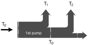
| TE perm. | Nm | 468 | 648 | 824 | 1044 | 1448 | 1448 | 2226 | 2787 | |
| Φ32 | Φ35 | Φ40 | Φ45 | Φ50 | Φ50 | Φ55 | Φ60 | |||
| at Z shaft end
DIN 5480 |
TE perm. | Nm | 912 | 912 | 1460 | 2190 | 3140 | 3140 | 3140 | 5780 |
| W35 | W35 | W40 | W45 | W50 | W50 | W50 | W60 | |||
| at S shaft end
ANSI B92.1a-1976 (SAE J744) |
TE perm. | Nm | 314 | 602 | 602 | 1640 | 1640 | 1640 | 1640 | 1640 |
| 1in | 1 1/4in | 1 1/4in | 1 3/4in | 1 3/4in | 1 3/4in | 1 3/4in | 1 3/4in | |||
| at T shaft end
ANSI B92.1a-1976 (SAE J744) |
TE perm. | Nm | 602 | 970 | 970 | - | - | - | 2670 | 4070 |
| 1 1/4 in | 1 3/8 in | 1 3/8 in | - | - | - | 2 in | 2 1/4 in | |||
| Through drive torque, max.3) | TD perm. | Nm | 314 | 521 | 660 | 822 | 1110 | 1110 | 1760 | 2065 |
1)Efficiency not considered
2) For drive shafts with no radial force
3) Observe max. input torque for shaft S!
Torque distribution
Determining the nominal value
| Flow | qv=(Vg ∙ n ∙ ηv) / 1000 | I/min |
| Torque | T=(Vg ∙ Δp) / 20 ∙ π ∙ ηmh | Nm |
| Power | P=(2π ∙ T ∙ n)/60000=(qv ∙ Δp)/600 ∙ ηt | kW |
Vg = Displacement per revolution in cm3
Δp = Differential pressure in bar
n = Speed in rpm
ηv = Volumetric efficiency
ηmh = Mechanical-hydraulic efficiency
ηt = Overall efficiency (nt= nv* nmh)
