Wenzhou Prance Hydraulic Equipment Co., Ltd.

cURL Too many subrequests by single Worker invocation. To configure this limit, refer to https://developers.cloudflare.com/workers/wrangler/configuration/#limits
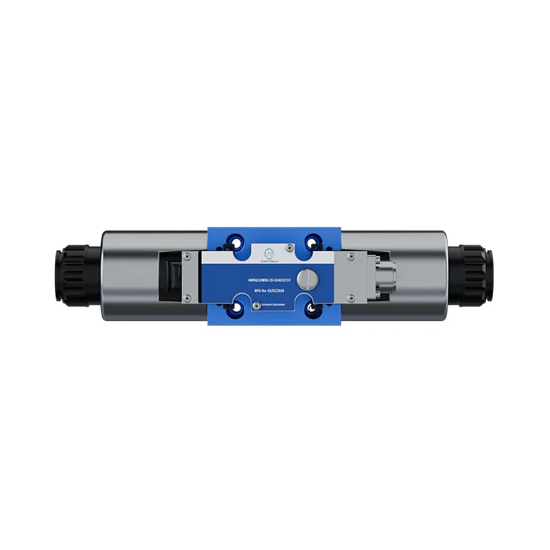
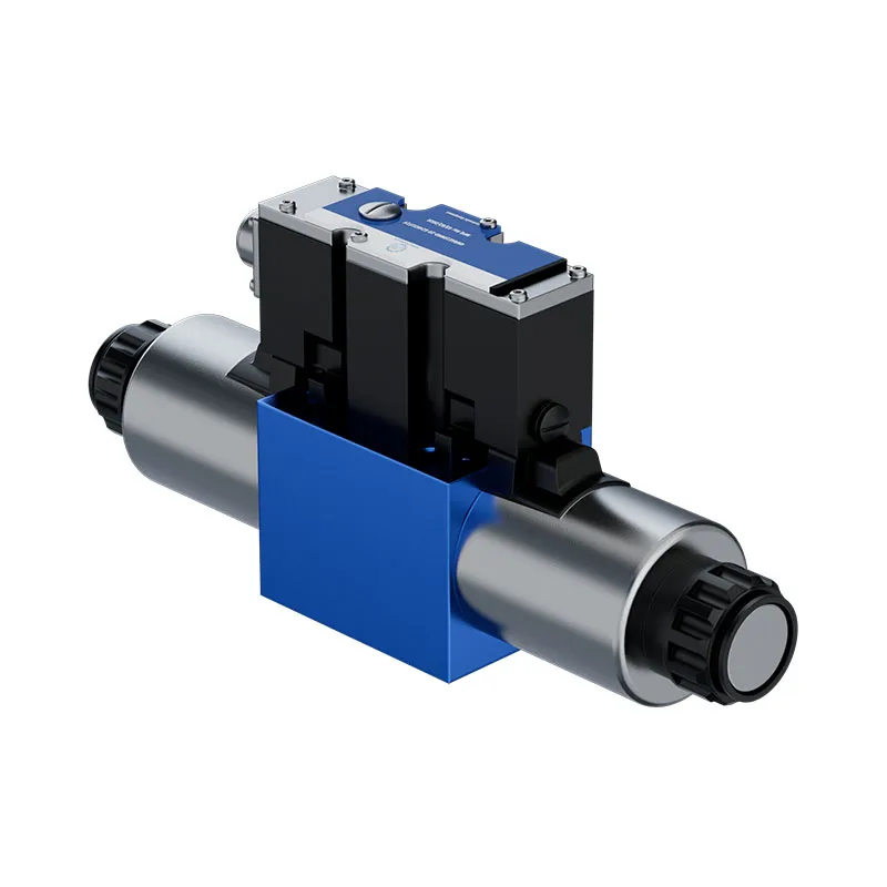
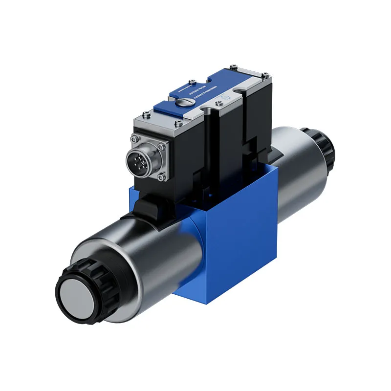
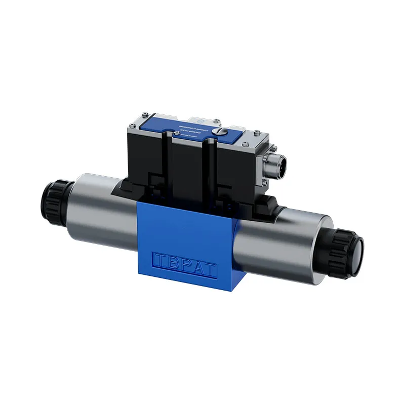
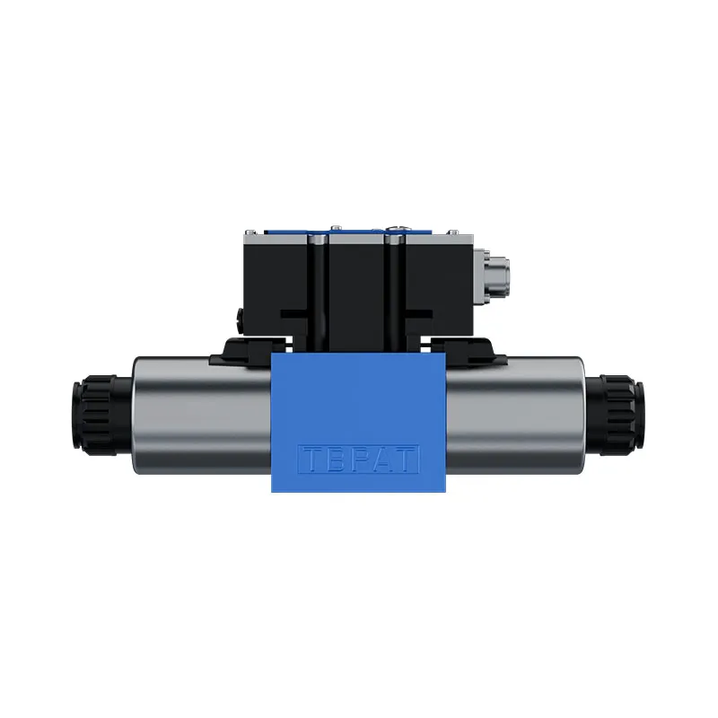
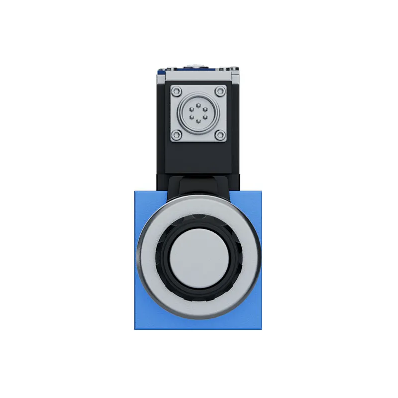
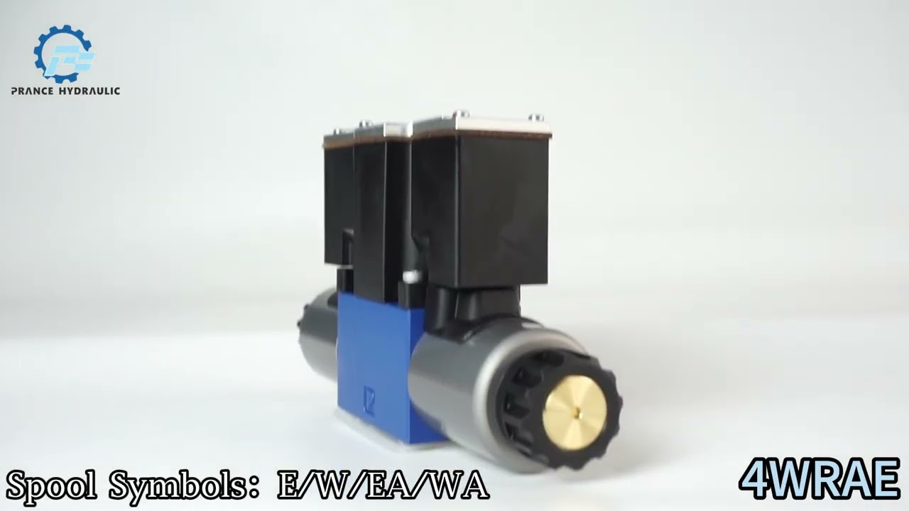
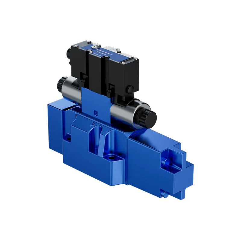
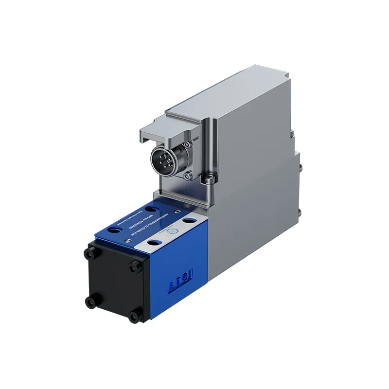
The 4WRAE proportional valve controls hydraulic direction and flow by direct actuation. The series table includes both WRA and WRAE versions; the WRAE integrated-electronics data must be used when matching the controller and connector.
- Direct actuation
- Spring-centered control spool
- Integrated electronics for WRAE variant
- Subplate mounting
PRANCE HYDRAULIC · PRODUCT SERIES
cURL Too many subrequests by single Worker invocation. To configure this limit, refer to https://developers.cloudflare.com/workers/wrangler/configuration/#limits
Direct-operated proportional directional valve · Subplate-mounted direction and flow control
The 4WRAE proportional valve controls hydraulic direction and flow by direct actuation. The series table includes both WRA and WRAE versions; the WRAE integrated-electronics data must be used when matching the controller and connector.
Model
✓
Request a QuotationTechnische Daten & Datenblatt anzeigen4WRAEDirect-operated proportional directional valve
Confirm the complete model and approved specification with Prance Hydraulic. Product-series references alone do not establish interchangeability.
Configuration review · Technical documentation · Product selection
Produktdetails
- Direct actuation
- Spring-centered control spool
- Integrated electronics for WRAE variant
- Subplate mounting
CATEGORIES: Hydraulikventil, Proportionalventil
4WRAE Features & Application
Direct actuation
Specify the full MS order code, installation drawing and operating duty so the quotation can identify the proposed configuration.
Spring-centered control spool
Match the complete control option and its command requirements to the existing controller. Similar housings can use different control arrangements.
Integrated electronics for WRAE variant
Match the complete control option and its command requirements to the existing controller. Similar housings can use different control arrangements.
Subplate mounting
Check pilot diameter, bolt pattern, shaft engagement or port pattern against the approved installation drawing.
4WRAE Specifications
| Series / model | 4WRAE |
|---|---|
| Product type | cURL Too many subrequests by single Worker invocation. To configure this limit, refer to https://developers.cloudflare.com/workers/wrangler/configuration/#limits |
| Design | Direct-operated proportional directional valve |
| Circuit / selection | Subplate-mounted direction and flow control |
| Published nominal sizes | 6 and 10 |
| Listed WRAE command variants | A1: ±10 V; F1: 4–20 mA |
| Rated-flow test condition | Δp = 10 bar in the existing technical table |
4WRAE Selection & Configuration
The 4WRAE proportional valve controls hydraulic direction and flow by direct actuation. The series table includes both WRA and WRAE versions; the WRAE integrated-electronics data must be used when matching the controller and connector.
Confirm nominal size, spool characteristic and command input before choosing a rated flow. Rated flow is given at a specified pressure drop and is different from maximum permissible flow. Keep the WRA and WRAE electrical data separate during comparison.
cURL Too many subrequests by single Worker invocation. To configure this limit, refer to https://developers.cloudflare.com/workers/wrangler/configuration/#limits.
cURL Too many subrequests by single Worker invocation. To configure this limit, refer to https://developers.cloudflare.com/workers/wrangler/configuration/#limits.
Hydraulic pumps · Hydraulic motors · Hydraulic valves
Send the MS nameplate, operating requirements and installation drawing for a configuration review before quoting.
- Model review — send the full model code or an existing nameplate photograph.
- Interface matching — confirm shaft, mounting flange, rotation and ports.
- Operating conditions — provide flow, pressure, speed, fluid and duty cycle.
- Documentation — request the relevant product data and drawings for your review.

4WRAE Buying Guide
Use this sequence to prepare the 4WRAE configuration for review and quotation.
- Select the circuit symbol and required de-energized spool position.
- State working flow, pressure and the pressure-drop condition for rated flow.
- Review spool overlap and command behavior during startup and switch-off.
- Confirm nominal size, subplate pattern, port and seal requirements.
- Match supply voltage, command input, connector and pin assignment.
- Review pilot supply, drain and feedback where the selected valve uses them.
- Approve the exact valve code, circuit drawing, quantity and documentation.
Selection, Documentation & Project Support

Selection Support
Learn more →Share your hydraulic circuit, operating point and installation requirements for a configuration discussion.
Flow · Pressure · Speed · Interfaces

Technical Resources
Learn more →Review product documentation, model codes and technical data before finalizing the specification.
Datasheets · Model codes · Drawings

Project Inquiries
Learn more →Send your required model, quantity, application and project requirements to discuss your inquiry.
Product inquiries · Configuration review
Configuration, Quantity & Delivery
Confirm the complete MS code, approved drawing and operating limits. Availability, quantity, documentation and delivery date are confirmed in the quotation.
Discuss Your 4WRAE Application
Send the full model code, operating duty, installation details and quantity.
Request a 4WRAE Quotation4WRAE Questions Before Ordering
What type of product is the 4WRAE?
4WRAE Direct Operated Proportional Valve. Design: Direct-operated proportional directional valve. Subplate-mounted direction and flow control. Confirm the complete order code for the offered version.
Can a similar valve replace the 4WRAE?
cURL Too many subrequests by single Worker invocation. To configure this limit, refer to https://developers.cloudflare.com/workers/wrangler/configuration/#limits.
cURL Too many subrequests by single Worker invocation. To configure this limit, refer to https://developers.cloudflare.com/workers/wrangler/configuration/#limits
Select the circuit symbol and required de-energized spool position. State working flow, pressure and the pressure-drop condition for rated flow. Attach the nameplate, complete order code, installation drawing and required quantity.
4WRAE Technical Data & Documents
View 4WRAE catalog data and operating conditions
cURL Too many subrequests by single Worker invocation. To configure this limit, refer to https://developers.cloudflare.com/workers/wrangler/configuration/#limits.
Technische Daten
(für Anwendungen außerhalb dieser Parameter sprechen Sie uns bitte an!)Allgemein
| Nennmaß | NS | 6 | 10 | |
| Installation | optional, vorzugsweise horizontal | |||
| Lagertemperaturbereich | ℃ | -20 bis +80 | ||
| Ambient | 4WRA | ℃ | -20 bis +70 | |
| Temperaturbereich | 4WRAE | ℃ | -20 bis +50 | |
| Gewicht | 4WRA | kg | 2.0 | 6.6 |
| 4WRAE | kg | 2.2 | 6.8 | |
| Hydraulisch (gemessen mit HLP46, ΘÖl= 40 ℃±5 ℃) | ||||
| Max. Betriebsdruck | Anschlüsse A, B, P | Bar | 315 | |
| Hafen T | Bar | 210 | ||
| Nennvolumenstrom qIn Venedig bei Δp = 10 bar | l/min | 7,15,26 | 30,60 | |
| Max. zulässiger Durchfluss | l/min | 42 (80)1) | 75 (140)1) | |
| Druckflüssigkeit | mineral oil (HL, HLP) to DIN 51524 other pressure fluids on request! | |||
| Temperaturbereich des Druckfluids | ℃ | -20 bis +80 (vorzugsweise +40 bis +50) | ||
| Viskositätsbereich | mm2/s | 20 bis 380 (vorzugsweise 30 bis 46) | ||
| Max. zulässiger Verschmutzungsgrad der Druckflüssigkeit Reinheitsklasse nach ISO 4406 (c) | Klasse 20/18/15 2) | |||
| Hysterese | % | ≤ 5 | ||
| Umkehrfehler | % | ≤ 1 | ||
| Antwortsensitivität | % | ≤ 0,5 | ||
Elektrisch
| Nennmaß | NS | 6 | 10 | |
| Spannungsart | Gleichstrom | |||
| Befehlswertsignal | Voltage input “A1” | V | ±10 | |
| mit Typ WRAE | Current input “F1” | mA | 4 bis 20 | |
| Max. Strom pro Magnetventil | A | 2.5 | ||
| Magnetspule | Kaltwert bei 20 ℃ | Ω | 2 | |
| Widerstand | Max. Warmwert | Ω | 3 | |
| Pflicht | % | 100 | ||
| Max. Spulentemperatur 1) | ℃ | 150 | ||
| Electrical connections see page 7 | 4WRA | mit Gerätestecker nach DIN EN 175301-803 oder ISO 4400 | ||
| Steckverbinder nach DIN EN 175301-803 oder ISO 4400 2) | ||||
| 4WRAE | mit Gerätestecker nach DIN EN 175201-804 | |||
| Steckverbinder DIN EN 175201-804 2) | ||||
| Ventilschutz nach EN 60529 | IP65 mit montiertem und festem Steckverbinder | |||
Steuerelektronik
| Für 4WRA | Digitalverstärker im Europakartenformat 2) | VT-VSPD-1-2X (to RE 30523 – middle of 2006) | |
| Analoger Verstärker im Europakartenformat 2) | VT-VSPA2-1-2X/… to RE 30110 | ||
| Analog-Modulverstärker 2) | VT-MSPA2-1-1X zu RE 30228 | ||
| Für 4WRAE | Analoges Sollwertmodul | in die Ventile integriert, siehe Seite 8 | |
| VT- SWMA-1-1X/… to RE 29902 | |||
| Analoges Sollwertmodul | VT-SWMKA-1-1X/… to RE 29903 | ||
| Digitale Sollwertkarte | VT-HACD-1-1X/… to RE 30143 | ||
| Analoge Sollwertkarte | VT-SWKA-1-1X/… to RE 30255 | ||
| Supply voltage 4WRAE, 4WRA 3) | Nennspannung | VDC | 24 |
| Unterer Grenzwert | V | 21 / 22 (4WRA); 19 (4WRAE) | |
| Oberer Grenzwert | V | 35 | |
| Verstärkerstrom | lMax | A | 1.8 |
| Verbrauch | Maximaler Stoßstrom | A | 3 |
Hinweis:
Details zum Umweltsimulationstest bezüglich EMV (elektromagnetische Verträglichkeit), Klima- und mechanischer Belastung entnehmen Sie bitte der RE 29055-U (Konformitätserklärung zur Umweltverträglichkeit).Watch 4WRAE Product Video
Related Selection Resources
Request a 4WRAE Quotation
Tell us your required configuration, quantity and application.
Ähnliche Produkte
cURL Too many subrequests by single Worker invocation. To configure this limit, refer to https://developers.cloudflare.com/workers/wrangler/configuration/#limits.

Technische Daten
(für Anwendungen außerhalb dieser Parameter sprechen Sie uns bitte an!)
Allgemein
| Nennmaß | NS | 6 | 10 | |
| Installation | optional, vorzugsweise horizontal | |||
| Lagertemperaturbereich | ℃ | -20 bis +80 | ||
| Ambient | 4WRA | ℃ | -20 bis +70 | |
| Temperaturbereich | 4WRAE | ℃ | -20 bis +50 | |
| Gewicht | 4WRA | kg | 2.0 | 6.6 |
| 4WRAE | kg | 2.2 | 6.8 | |
| Hydraulisch (gemessen mit HLP46, ΘÖl= 40 ℃±5 ℃) | ||||
| Max. Betriebsdruck | Anschlüsse A, B, P | Bar | 315 | |
| Hafen T | Bar | 210 | ||
| Nennvolumenstrom qIn Venedig bei Δp = 10 bar | l/min | 7,15,26 | 30,60 | |
| Max. zulässiger Durchfluss | l/min | 42 (80)1) | 75 (140)1) | |
| Druckflüssigkeit | Mineralöl (HL, HLP) nach DIN 51524 Andere Druckflüssigkeiten auf Anfrage! |
|||
| Temperaturbereich des Druckfluids | ℃ | -20 bis +80 (vorzugsweise +40 bis +50) | ||
| Viskositätsbereich | mm2/s | 20 bis 380 (vorzugsweise 30 bis 46) | ||
| Max. zulässiger Verschmutzungsgrad der Druckflüssigkeit Reinheitsklasse nach ISO 4406 (c) | Klasse 20/18/15 2) | |||
| Hysterese | % | ≤ 5 | ||
| Umkehrfehler | % | ≤ 1 | ||
| Antwortsensitivität | % | ≤ 0,5 | ||
1) zulässiger Volumenstrom mit zwei Strömungswegen
2) Die für die Komponenten angegebene Sauberkeitsklasse muss in Hydrauliksystemen eingehalten werden. Eine wirksame Filtration verhindert das Auftreten von Störungen und erhöht gleichzeitig die Lebensdauer der Komponenten. Zur Auswahl von Filtern siehe die Datenblätter RE 50070, RE 50076, RE 50081, RE 50086 und RE 50088.
Elektrisch
| Nennmaß | NS | 6 | 10 | |
| Spannungsart | Gleichstrom | |||
| Befehlswertsignal | Spannungseingang "A1" | V | ±10 | |
| mit Typ WRAE | F1" | mA | 4 bis 20 | |
| Max. Strom pro Magnetventil | A | 2.5 | ||
| Magnetspule | Kaltwert bei 20 ℃ | Ω | 2 | |
| Widerstand | Max. Warmwert | Ω | 3 | |
| Pflicht | % | 100 | ||
| Max. Spulentemperatur 1) | ℃ | 150 | ||
| Elektrische Anschlüsse siehe Seite 7 |
4WRA | mit Gerätestecker nach DIN EN 175301-803 oder ISO 4400 | ||
| Steckverbinder nach DIN EN 175301-803 oder ISO 4400 2) | ||||
| 4WRAE | mit Gerätestecker nach DIN EN 175201-804 | |||
| Steckverbinder DIN EN 175201-804 2) | ||||
| Ventilschutz nach EN 60529 | IP65 mit montiertem und festem Steckverbinder | |||
Steuerelektronik
| Für 4WRA | Digitalverstärker im Europakartenformat 2) | VT-VSPD-1-2X (zu RE 30523 - Mitte 2006) | |
| Analoger Verstärker im Europakartenformat 2) | VT-VSPA2-1-2X/... zu RE 30110 | ||
| Analog-Modulverstärker 2) | VT-MSPA2-1-1X zu RE 30228 | ||
| Für 4WRAE | Analoges Sollwertmodul | in die Ventile integriert, siehe Seite 8 | |
| VT- SWMA-1-1X/... nach RE 29902 | |||
| Analoges Sollwertmodul | VT-SWMKA-1-1X/... zu RE 29903 | ||
| Digitale Sollwertkarte | VT-HACD-1-1X/... zu RE 30143 | ||
| Analoge Sollwertkarte | VT-SWKA-1-1X/... zu RE 30255 | ||
| Versorgungsspannung 4WRAE, 4WRA 3) |
Nennspannung | VDC | 24 |
| Unterer Grenzwert | V | 21 / 22 (4WRA); 19 (4WRAE) |
|
| Oberer Grenzwert | V | 35 | |
| Verstärkerstrom | lMax | A | 1.8 |
| Verbrauch | Maximaler Stoßstrom | A | 3 |
Aufgrund der auftretenden Oberflächentemperatur der Magnetspulen müssen die europäischen Normen DIN EN 563 und DIN EN 982 berücksichtigt werden!
2) Getrennte Bestellung
3) Mit Steuerungselektronik von Bosch Rexroth AG
Hinweis:
Details zum Umweltsimulationstest bezüglich EMV (elektromagnetische Verträglichkeit), Klima- und mechanischer Belastung entnehmen Sie bitte der RE 29055-U (Konformitätserklärung zur Umweltverträglichkeit).
